910-0001-00-MAN-R06 FLIR Proprietary Information Page 31 of 81
Information contained in this document pertains to a Canadian origin product that is controlled as "dual use" by the Canadian
government. However, when in the United States or possessed by a US person, it may be considered a defense article from the US Government's
perspective. US government authorization may be required for re-transfer to a foreign person. If you have any questions, please contact FLIR's
Global Trade Compliance group at exportquestions@flir.com .
2.2.5.3 Creating a Zone
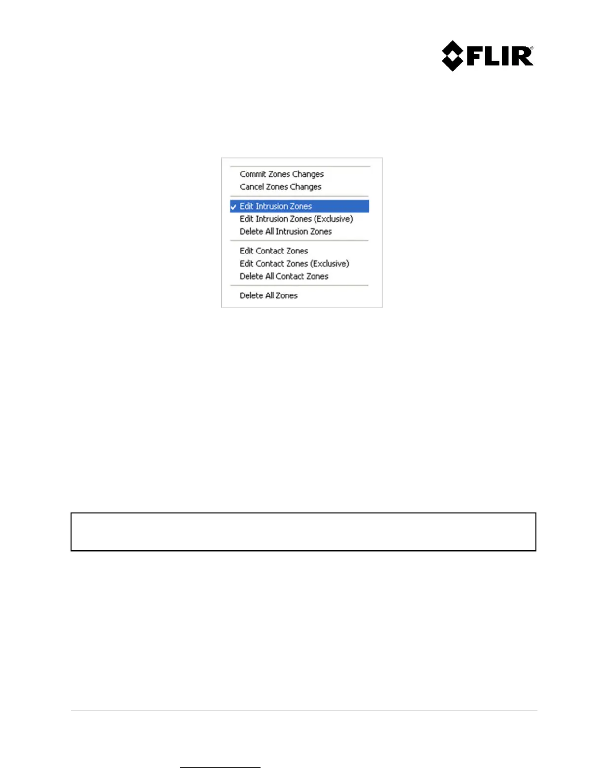
Using the Edit menu, select the type of zone to create (intrusion, exclusive intrusion, contact or
exclusive contact), as shown in Figure 16. The mouse cursor will then change to a diamond () shape.
Figure 16 – Edit Menu
A zone consists of a polygon made with three (3) or more sides. Each segment is added by left-clicking
with the mouse at the desired location. Figure 17 through Figure 20 shows a typical zone during the
edition process. The dashed line shows how the zone will be defined if the user completes the
command.
To start editing the zone, left-click with the mouse at the desired location on the PPI. This will create
a start control point, and a segment will be shown between this endpoint and the current mouse
location.
Subsequent left mouse clicks will create additional segments to the zone. While editing the zone, the
keyboard commands described in Table 3 can also be used.
Note
The angle between 2 vertexes cannot exceed 120º.
 Loading...