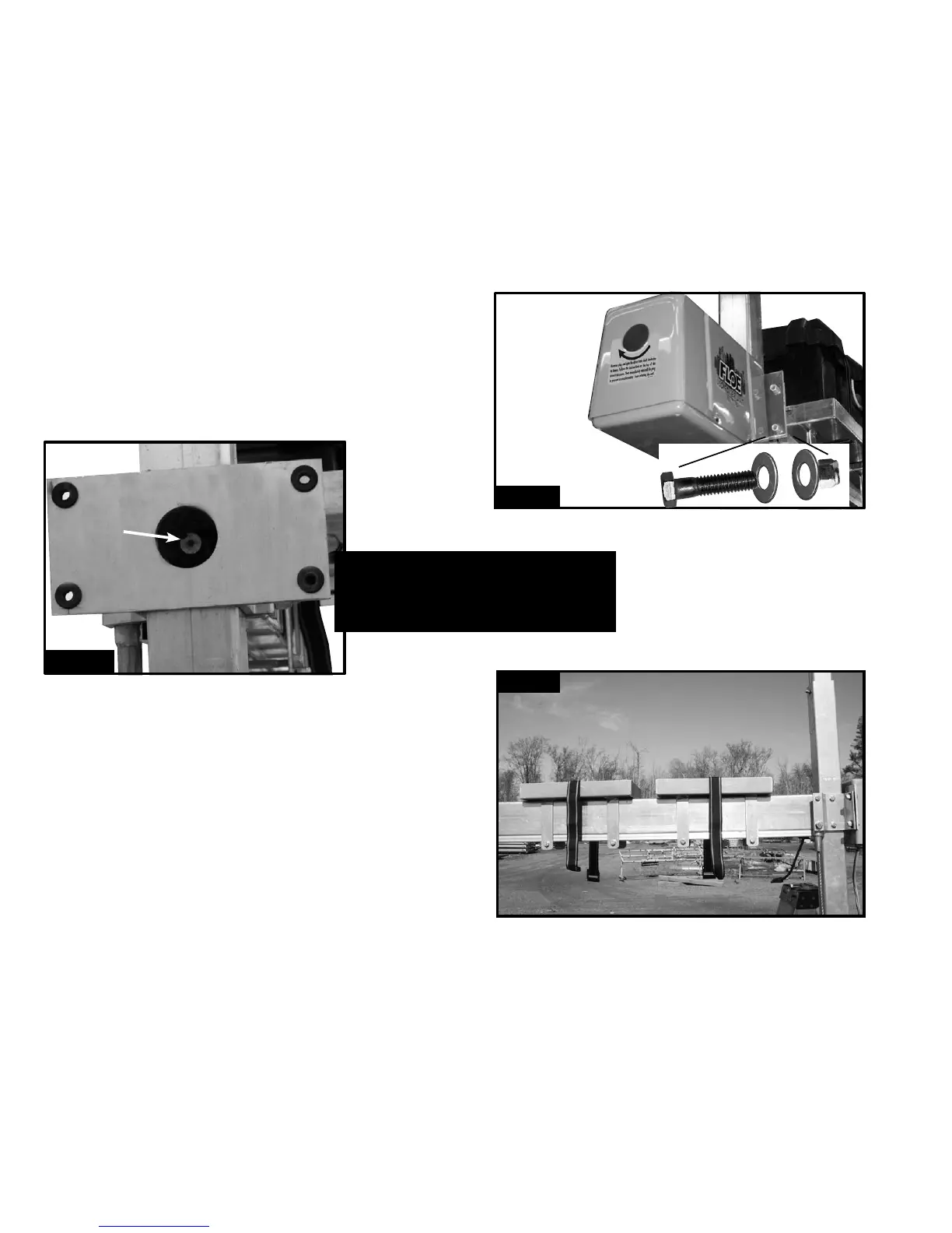
STEP 1 - - - - - - - - - - - - - - - -
With the lift frame assembly done the VSD Drive Train and electronics can now be installed.
Apply a generous amount of anti-seize to the inside of the rigid coupler (Fig. 1A). Then attach
the “VSD Power Unit” to the “ball screw clamp” using four 3/8” x 1 3/4” bolts, four nylock
nuts, and eight at washers as shown (Fig 1B). Torque to 10 ft/lbs. NOTE: The motor shaft
and the rigid coupler are keyed and must be aligned.
Fig. 1A
Apply anti-seize
Fig. 1B
Attach using four
3/8” x 1 3/4”
bolts, four nylock
nuts, and eight
at washers
- - - - - - - - - IMPORTANT - - - - - - - - -
Apply a generous amount of
Anti-Seize to the inside of the rigid
coupler attached to the Ball Screw.
STEP 2 - - - - - - - - - - - - -
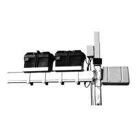
Attach the battery trays to the ball screw tube. The rst one 8” from the
corner post and the second 3” from the rst using the (4) 3/8 x 5 -1/2”
bolts and (4) 3/8” nylock nuts included with the lift frame hardware. The
offset side of the battery tray should be positioned to the outside of the lift
to provide clearance inside the lift. (Fig. 2) Torque to 25 ft/lbs.
Page 4 of 8
Fig. 2