EasyManua.ls Logo

Floe 3800 User Manual

Floe 3800
8 pages
To Next Page IconTo Next Page
Page #1 background imageLoading...
Page #1 background image
FLOE 24 vOLt vSD DrivE
3800, 5000, 6000, 6500 & 8000# LiFtS
P/Ns 511-38500-00, 511-60020-00, 511-80020-00
ASSEMBLY iNStrUCtiONS
TOOLS REQUIRED:
(2) 3/4” socket or wrench for 1/2”
nuts and bolts
(1) 9/16” socket or wrench for 3/8”
nuts and bolts
(1) Flat tip screwdriver
(1) Torque wrench
INSTRUCTION P/N: 611-50025-00
ISSUE DATE: 9/11/13
REVISED: 9/28/17
Manufactured By:
Floe International, Inc.
48473 State Hwy. 65
McGregor, MN 55760

Table of Contents

Question and Answer IconNeed help?

Do you have a question about the Floe 3800 and is the answer not in the manual?

Floe 3800 Specifications

General IconGeneral
Lift Capacity3800 lbs
Maximum Load Capacity3800 lbs
Power SourceHydraulic
Lifting Height72 inches
Dimensions48 x 30 x 72 inches

Summary

Step 1: Install VSD Drive Train and Electronics

Attach VSD Power Unit to Ball Screw Clamp

Secure VSD Power Unit using bolts, nuts, and washers. Align keyed motor shaft and coupler. Torque to 10 ft/lbs.

Step 2: Attach Battery Trays

Position and Secure Battery Trays

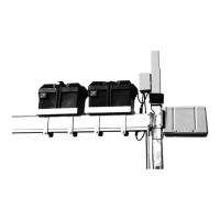
Attach battery trays to the ball screw tube using bolts and nuts. Position offset side outwards for clearance. Torque to 25 ft/lbs.

Step 3: Attach and Wire Advanced Switch Control

Mount ASC to Corner Post

Adhere dual lock 5-1/4" from top of corner post. Attach ASC to the post using provided hardware.

Connect ASC to VSD Power Unit

Connect four spade wires from ASC to VSD Power Unit. Ensure correct connections for larger wires.

Step 4: Connect ASC to Batteries

Wire ASC to Batteries and Interconnect

Connect red and black/red wires from ASC to battery posts. Connect battery interconnect cable and volt meter leads.

Step 5: Connect Wired Remote and Limit Switch

Connect Wired Remote to ASC

Plug the 4-connector wired remote into the ASC. Identify lead by blue wire tie.

Connect Limit Switch Lead to ASC

Plug the 4-connector limit switch lead into the ASC, identified by its protrusion.

Step 6: Secure Wired Remote

Route and Fasten Wired Remote

Secure loose wires and remote wire to lift structure using Velcro. Route remote along canopy frame and side of lift.

Related product manuals