Do you have a question about the Floe PWC1300 and is the answer not in the manual?
Lists essential tools such as socket wrenches and a torque wrench for installation.
Explicitly states not to use an impact wrench to prevent damage during assembly.
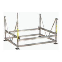
Remove bolts from leveling legs and insert into corner posts, aligning nut tracks.
Re-install bolts to secure leveling legs to the side frame and torque to specification.
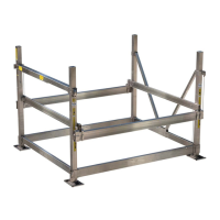
Position frame beams onto side frames and slide frame beam clamps onto each end.
Attach clamps to frame beams using specified bolts and nuts, torquing to 40 ft-lb.
Attach front braces to mounting tabs using bolts and nuts, torquing to 10 ft-lb.
Place pivot arms into mounts on frame beams and secure with bolts, washers, and nuts.
Position the cradle assembly onto the pivot arms.
Secure cradle to front and rear pivot arms using specified hardware.
Insert nut and washer into corner post and start bolt for winch post attachment.
Leave winch post 5" out of corner post and torque bolt to 35 ft-lb.
Mount the manual winch onto the post with the crank spindle on top.
Loosen and remove hardware from pulley assembly to insert the cable.
Attach 2" pulley assembly to the side frame beam weldment using specified hardware.
Thread the lifting cable through cradle pulley assemblies and attach to weldment.
Install 3" pulley assemblies using specified bolts and nuts, torquing to 10 ft-lb.
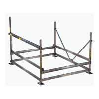
This document provides assembly instructions for the FLOE PWC1300 LIFT, a personal watercraft (PWC) lift designed with a patented Easy Level Leg System. The manual, identified by P/N 511-10000-00 and issued on 11/15/21, guides users through the installation process.
The FLOE PWC1300 LIFT is designed to safely store and launch personal watercraft. Its primary function is to lift a PWC out of the water for storage and lower it for use, protecting the watercraft from environmental elements and simplifying launching and docking. The patented Easy Level Leg System allows for easy adjustment of the lift's height and level, accommodating varying water depths and shoreline conditions.
Model: FLOE PWC1300 LIFT Part Number: 511-10000-00 Manufacturer: Floe International Inc., 48473 State Hwy. 65, McGregor, MN 55760 Website: www.floeintl.com
Tools Required for Assembly:
Important Note: Do not use an impact wrench during assembly to prevent damage to components.
Hardware Card Contents (511-04206-00): The assembly requires various bolts, nuts, and washers, categorized by step:
Step 1 Hardware:
Step 2 Hardware:
Step 3 Hardware:
Step 4 Hardware:
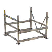
PWC-1300 Bill of Materials (511-10000-00): This list details the major components of the lift:
Easy Level Leg System: The lift incorporates a patented Easy Level Leg System, which simplifies the process of leveling the lift in varying water depths. This system likely involves adjustable legs that can be extended or retracted to achieve the desired height and stability.
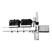
Winch Mounting Positions: The manual winch can be mounted on either the right or left side frame of the lift, offering flexibility based on user preference or dock setup. The assembly instructions detail the process for mounting on the left side, with the note that the same steps apply for right-side installation.
Safety Guidelines:
While the document primarily focuses on assembly, certain aspects imply maintenance considerations:
Torque Specifications: Specific torque values are provided for various bolts throughout the assembly process (e.g., 40 ft-lb for leveling legs and frame beam clamps, 10 ft-lb for front braces and pulley assemblies, 35 ft-lb for winch post). Adhering to these specifications is vital for the structural integrity and longevity of the lift, minimizing wear and tear.
"Do Not Overtighten" Warnings: For pivot arm and cradle attachments, the instructions explicitly state "DO NOT OVERTIGHTEN." This indicates that overtightening could damage components, suggesting that proper tensioning is a key aspect of maintenance to prevent premature failure.
"Tighten to Remove Excess Play" Instructions: For the cable insertion into the pulley assembly, the instruction to "tighten to remove excess play" highlights the importance of proper cable tension for efficient and safe operation. Regular checks for excess play in the cable system would be a crucial maintenance task.
The FLOE PWC1300 LIFT is designed for ease of assembly and reliable operation, with clear instructions to ensure safe and effective use for personal watercraft owners.
| Brand | Floe |
|---|---|
| Model | PWC1300 |
| Category | Lifting Systems |
| Language | English |