Do you have a question about the Floe V-2602 and is the answer not in the manual?
Defines symbols used in assembly diagrams for clarity and understanding.
Highlights critical safety notes, including a specific warning against impact wrench use.
Provides practical advice and best practices for a successful assembly process.
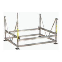
Specifies the lift's physical dimensions and the necessary workspace for assembly.
Details suitable materials and quantity for blocking the lift during assembly steps.
Guides the attachment of lift frame beams and various types of clamps.
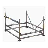
Details securing initial frame components using bolts and nuts.
Critical instruction on correct frame beam orientation before proceeding.
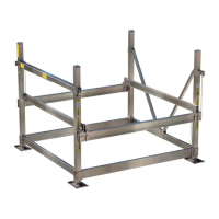
Guides attachment of corner posts and sand pads, with notes on bolt and sticker placement.
Details the process of securing corner posts to frame beams using bolts and nuts.
Provides specific torque settings for fasteners on corner posts A, B, C, and D.
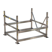
Guides installation of upper V-brace brackets and initial V-brace attachment.
Details fitting V-brace clamps and securing the V-braces with hardware.
Illustrates the final tightening of V-brace assemblies to specified torque.
Guides the installation of left and right side cradle assemblies onto the lift frame.
Details attaching end cradles and front/rear cradle beams using U-clamps.
Covers checking cradle gaps, ensuring flush surfaces, and applying final torque.
Guides the installation of the cable holder using specified hardware and torque.
Details correct cable holder orientation and the critical 120-degree installation angle.
| Brand | Floe |
|---|---|
| Model | V-2602 |
| Category | Lifting Systems |
| Language | English |