To be sure that starting relay will function and
that overload will not “nuisance trip”, install
control box vertically with top side up.
Wire control box as shown in Figures 1A and
1B. A 3-wire pump will not operate without
control box. Operation without control box will
burn out 3 wire motor.
Installation must include circuit and component
protection which meet local code and United
States National Electrical Code requirements.
If main overload trips, look for:
1. Shorted Capacitor
2. Voltage Problems
3. Overloaded or locked pump.
NOTICE: Match motor to control box as shown
below.
TABLE IV: Control Box Selection
4
HP Voltage Motor No. Control Box No.
1/2 230 G43A0005A2 FP217-810
3/4 230 G43A0007A2 FP217-811
1 230 G43A0010A2 FP217-812
1-1/2 230 G43A0015A2 FP3492
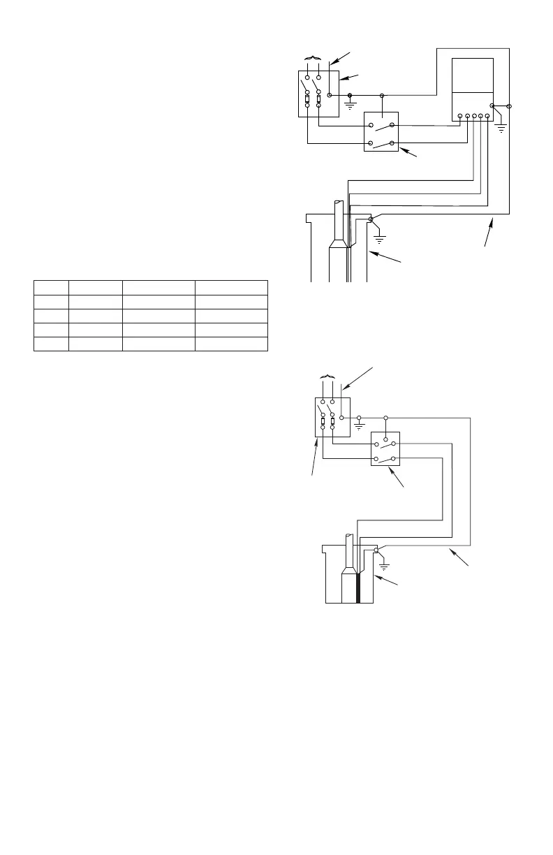
FIGURE 1A - 3-wire quick disconnect box. Follow
color coding when connecting control box (Yellow to
Y, Red to R, Black to B).
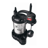
FIGURE 1B - Single phase, 2-wire connections. 2-wire
pumps have two power supply wire (Black) and one
ground wire (Green). Control box is not required. This
is correct connection information for 115 and 230 volt
2-wire motors only.