Valtek GS General Service Valve FCD VLENIM0300-00-A4 08/14
19
flowserve.com
O-ring
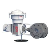
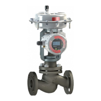
Positioner
Figure 14: Remove the positioner
240
345
76
113
249
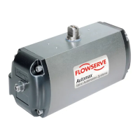
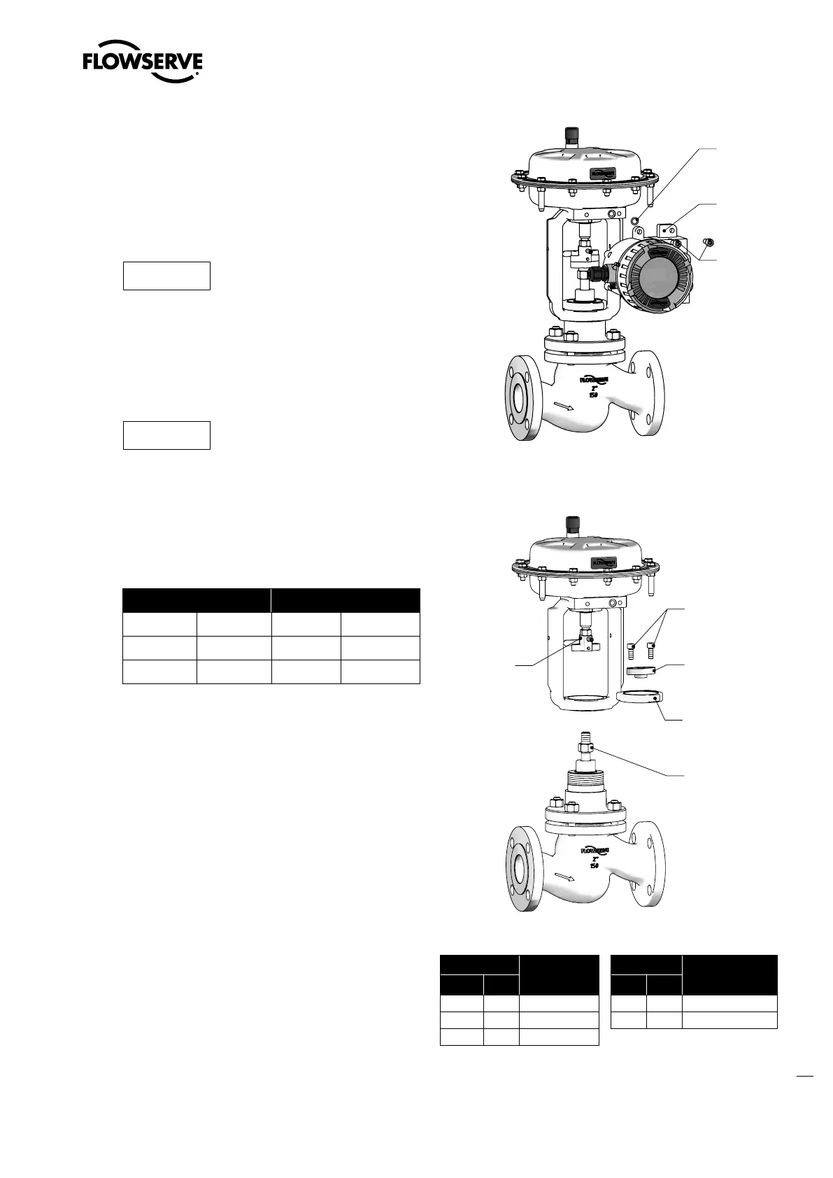
Figure 15: Remove the actuator
Item
Part
Item
Part
WW
1)
EU
2)
WW EU
76 5.10 Yoke lock nut 249 5.3 Upper coupling
113 5.2 Lock nut 345 5.1 Lower coupling
240 5.5 Cap screw
Table 16: Coupling parts identification
1)
WorldWide
2)
European Union
Reassemble the actuator and positioner
onto the valve:
1. Mount the pneumatic diaphragm or multi-turn actuator
onto the bonnet and tighten the yoke lock nut (76)
clockwise (See Section 14: Required Torques).
NOTICE
The legs of the yoke should be parallel
to the flow direction.
2. Move the actuator to the open position.
3. Screw in the lower coupling (345) three turns and
move the actuator into the closed position.
NOTICE
The plug must be aligned onto the
seat. The cushioning effect of the bel-
lows can be prevented by tightening the packing follower.
4. Move the actuator back into the open position and
adjust the distance between the lower coupling (345)
and upper coupling (249) by adjusting the stroke
length.
Size Stroke
15 - 50 1/2“ - 2“ 20
+ 0,5
mm 0.787
+ 0.02
in.
65 - 100 3“ - 4“
40
+ 0,5
mm 1.574
+ 0.02
in.
125 - 150 6“ 60
+ 0,8
mm 2.362
+ 0.03
in.
Table 15: Stroke adjustment length
5. Move the actuator to the close position and install the
cap screws (240).
6. Lock the lock nut (113). Keep upper coupling (249)
from turning by securing with a wrench.
7. Reassemble the positioner on the valve as necessary
(See relevant accessory User Instruction).
8. Connect the valve into the pipeline (See Section 9:
Installation).
9. After reinstalling the control valve into the pipeline,
perform three full strokes and check the tightness of
the packing follower and bonnet bolting (See Section
10: Valve Quick-Check).
10. Log the maintenance interval and the work performed.