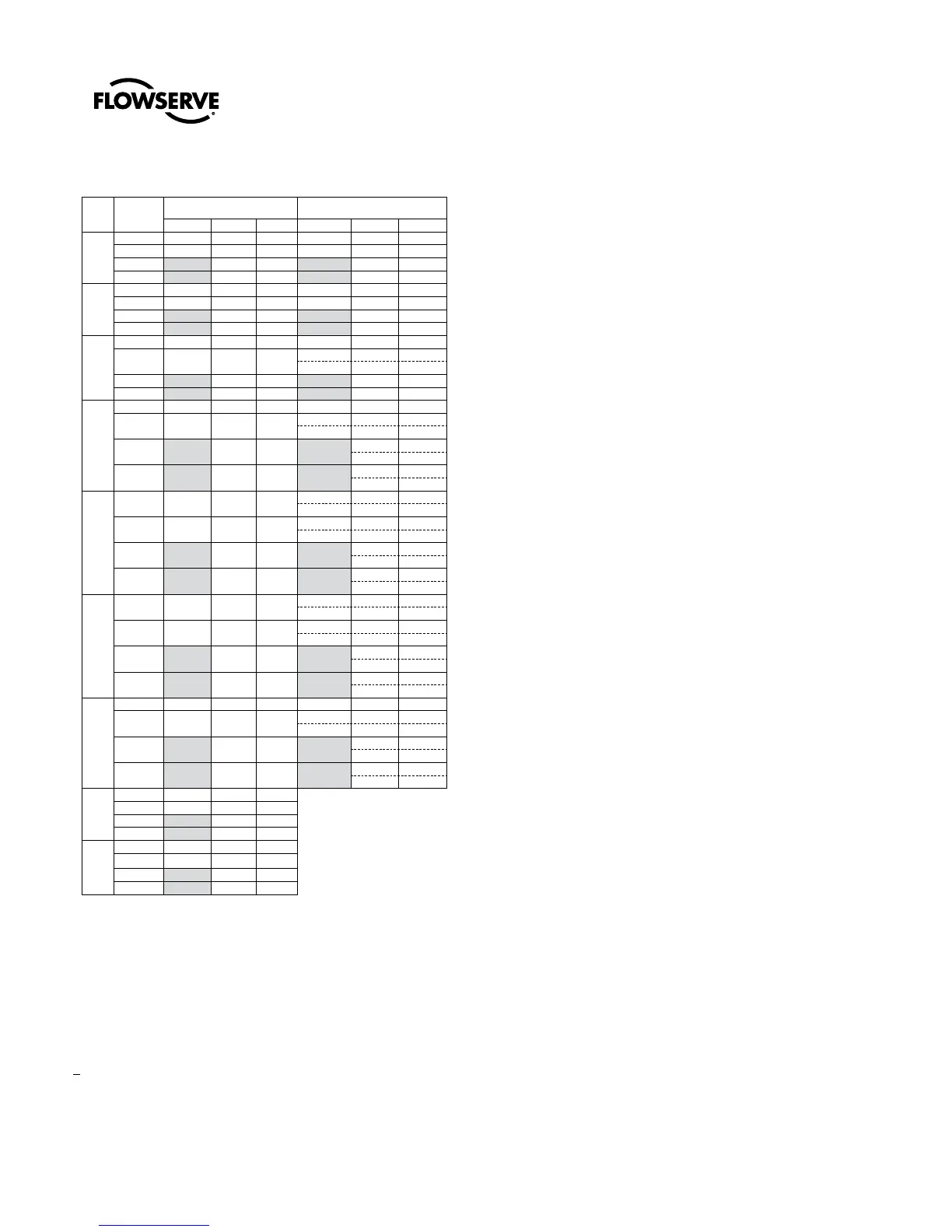
Table I: Line Flange Bolting Specifications
Valve
size
Nominal
Pressure /
Rating
MaxFlo 4 flanged
Size x Length
MaxFlo 4 flangeless
Size x Length
Inches Metric Qty/ valve Inches Metric Qty/ valve
DN25
1"
ANSI 150 1/2 X 2.62 M12 X 65 8 1/2 X 6.75 M12 X 170 4
ANSI 300 5/8 X 3.12 M16 X 80 8 5/8 X 6.88 M16 X 175 4
PN 16 M12 X 70 8 M12 X 175 4
PN 40 M12 X 70 8 M12 X 175 4
DN40
1½"
ANSI 150 1/2 X 2.88 M12 X 70 8 1/2 X 7.50 M12 X 190 4
ANSI 300 3/4 X 3.62 M20 X 95 8 3/4 X 8.38 M20 X 215 4
PN 16 M16 X 80 8 M16 X 200 4
PN 40 M16 X 80 8 M16 X 200 4
DN50
2"
ANSI 150 5/8 X 3.25 M16 X 85 8 5/8 X 8.38 M16 X 215 4
ANSI 300 5/8 X 3.5 M16 X 90 16
5/8 X 3.50 M16 X 90 4
5/8 X 8.50 M16 X 220 6
PN 16 M16 X 85 8 M16 X 215 4
PN 40 M16 X 85 8 M16 X 215 4
DN80
3"
ANSI 150 5/8 X 3.62 M16 X 95 8 5/8 X 10.5 M16 X 265 4
ANSI 300 3/4 X 4.25 M20 X 110 16
3/4 X 4.25 M20 X 110 4
3/4 X 11.00 M20 X 280 6
PN 16 M16 X 85 16
M16 X 85 6
M16 X 255 5
PN 40 M16 X 95 16
M16 X 95 6
M16 X 265 5
DN100
4"
ANSI 150 5/8 X 3.62 M16 X 95 16
5/8 X 3.62 M16 X 95 4
5/8 X 11.5 M16 X 295 6
ANSI 300 3/4 X 4.5 M20 X 115
16 3/4 X 4.5 M20 X 115 4
3/4 X 12.25 M20 X 315 6
PN 16 M16 X 85 16
M16 X 85 6
M16 X 285 5
PN 40 M20 X 100 16
M20 X 100 6
M20 X 300 5
DN150
6"
ANSI 150 3/4 X 3.75 M20 X 105 16
3/4 X 3.75 M20 X 105 4
3/4 X 13.25 M20 X 340 6
ANSI 300 3/4 X 4.88 M20 X 125 24
3/4 X 4.88 M20 X 125 8
3/4 X 14.00 M20 X 360 8
PN 16 M20 X 100 16
M20 X 100 4
M20 X 335 6
PN 40 M24 X 115 16
M24 X 115 4
M24 X 350 6
DN200
8"
ANSI 150 3/4 X 4.25 M20 X 110 16 3/4 X 4.25 M20 X 360 8
ANSI 300 7/8 X 5.5 M22 X 140 24
7/8 X 5.5 M22 X 140 4
7/8 X 15.19 M22 X 390 10
PN 16 M20 X 100 24
M20 X 100 8
M20 X 350 8
PN 40 M27 X 135 24
M27 X 135 8
M27 X 385 8
DN250
10"
ANSI 150 7/8 X 4.62 M22 X 120 24
ANSI 300 1 X 6.25 M24 X 155 32
PN 16 M24 X 110 24
PN 40 M30 X 150 24
DN300
12"
ANSI 150 7/8 X 4.75 M22 X 120 24
ANSI 300 1 1/8 X 6.75 M27 X 170 32
PN 16 M24 X 115 24
PN 40 M30 X 160 32
4 Quick-Check
Before commissioning, check the control valve by following these steps:
4.1 Check for full stroke by varying the instrument signal settings
appropriately. Observe the plug position indicator located on the
actuator or the positioner. The plug should change position with
a smooth turning movement.
4.2 Check all air connections for leaks. Tighten or replace any
leaking lines.
4.3 Check packing box bolting for proper tightness.
a CAUTION: Do not overtighten packing box bolting. This can
cause excessive packing wear and high stem friction that may
impede shaft movement. After the valve has been in service for
a short period, recheck the packing-box nuts. If the packing-box
leaks, tighten the nuts just enough to stop the leak.
4.4 Make sure the valve fails in the correct direction in case of air
failure. This is done by positioning the valve at mid-stroke and
turning off the air supply and observing the failure direction.
If the action is incorrect, see the section “Reversing the
Air-action” in the instructions of the installation, operation and
maintenance manual of the appropriate actuator.
5 Preventative Maintenance
At least once every six months, check for proper operation by following
the preventative maintenance steps outlined below. These steps may be
performed while the valve is in-line and without interrupting service. If
an internal problem is suspected, refer to section “Valve Disassembly”.
5.1 Look for signs of gasket leakage through the end flanges and
bonnet. If necessary, re-torque flange, bonnet and post bolting.
5.2 Examine the valve for damage, such as damage caused by
corrosive fumes or process drippings.
5.3 Clean the valve and repaint areas of severe oxidation.
5.4 Check the packing-box for proper tightness. If there is a persis-
tent leak, change the packing after referring to sections “Valve
Disassembly and Body Reassembly”.
a CAUTION: Do not overtighten packing box bolting. This can
cause excessive packing wear and high friction that may impede
shaft movement.
5.5 If the valve is equipped with a lubricator, add lubricant if necessary.
5.6 If possible, stroke the valve and check for smooth, full-stroke
operation. Unsteady shaft movement may indicate an internal
valve problem.
5.7 Check the calibration of the positioner. For further preventative
maintenance, see the instructions in the installation, operation
and maintenance manual for the applicable positioner.