15
14. AUTOMATIC ON/OFF SWITCHING
If Flowtrecs is switched off with OFF butto or automatically and
if the RPM measurement is connected, after starting the engine
automatic switch
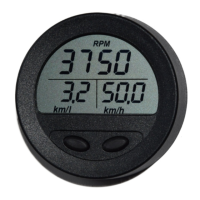
on will take place, setting the screen
to RPM and Speed read-out. After turning engine off,
RPM and Speed read-out will be replaced by Time and
Any subsequent engine start-up will revert the screen
to RPM reading. Manual change of the top screen readings
is possible at any time by pressing both buttons simultaneously.
15. INSTALLATION RECOMMENDATION
.
16
Flowtrec Mini unlike other gauges doesn't require cutting out large mounting hole since it is adapted
to mounting it on the surface of control console. It's enough to make a few openings of a small diameter
and secure it with nuts from behind the console. One of the openings (the middle one) should have
the diameter of 9-10mm for running a bundle of wires through it and the other two 3-4mm each.
It's important for the dividing line of openings to run horizontally because it determines the position
of the display on the console and if it slopes, the screen on the console will slope as well. After drilling
the openings we unscrew and put through the large opening the fuse rim which is in the wire bundle,
The next step is to connect together the 3 quick couplings coming out of the bundle with couplings
from the connecting box . Colour compatibility of connected wires must be preserved. Into the socket
which is coming out of connecting box we insert the cable plug to connect the sensor and t his
connection we secure with insulation tape to prevent the impact of water and damp. If the function
of engine's RPM measurement is used, we connect the green wire to the output of tacho signal in
shifter or another tachometer ( if it's installed). If not the green wire can be left disconnected .
The other end of the extension cable to sensor we connect to the fuel sensor and this connection must
be secured against water impact. At the end we connect device's earth (ground) - (black wire) to
the negative voltage pole from the battery and the red voltage wire to positive voltage
pole ( +12VDC)
Flow sensor should be installed in fuel line between the engine and the fuel tank, as indicated in picture
on p. 20. The fuel hose which can be connected to sensor should have internal diameter 8-9mm (3/8").
After cutting fuel hose , push its ends onto the fuel sensor ends paying attention to consistency of fuel
flow direction with the direction of an arrow on sensor's case and securing it against sliding with nylon
clamps. Then insert sensor's plug into the extension cable socket and fix the sensor along fuel lines
in horizontal position so that the hoses are leading out horizontally and the upper
surface of sensor is
in horizontal position. The sensor should be placed above the fuel tank so that in case of fuel lines
loosening, there will be no fuel leak. .
Having fixed the sensor we must spill it ( remove the air from its inside which gets into fuel system
while installing). To do this using bulb primer for sucking fuel, we must pump some amount of fuel
through the sensor. While spilling, the LED control visible inside the sensor should be flashing
(if the sensor is connected to a clock and the clock is on). With
low volume flow it is visible as a green
blinking light. With large volume flow the blinking disappears and a steady light can be observed.
A correct operation of sensor is confirmed by LED blinking during the flow of fuel.
16.INSTALLING FLOW SENSOR
It should be also located away from area where it will be effected by excessive heat or vibration from the
engine.
Voltage readings.
If fuel sensor is installed in open space ( under daylight operation) it should be secured against
light using f.ex. black stretch foil. Under the strong light influence, they may not work correctly !
 Loading...