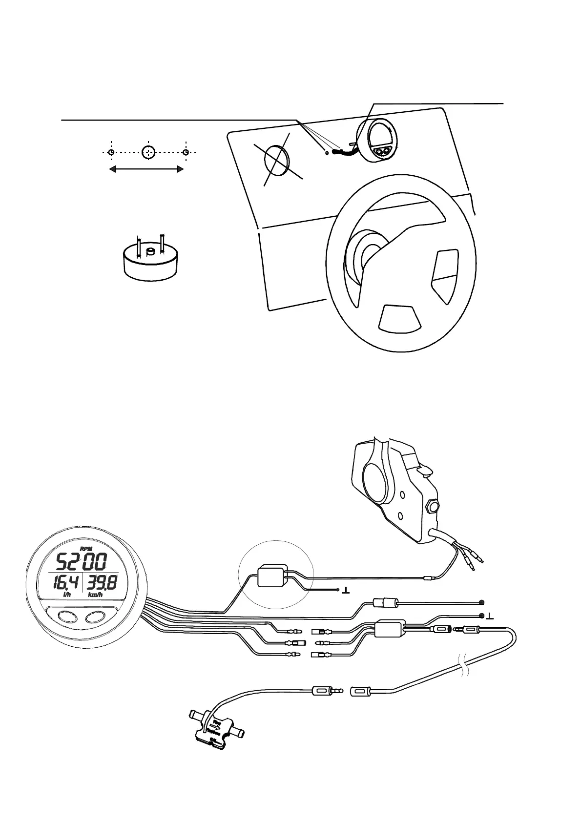
Small mounting holes 1x9mm + 2x4mm
instead of a large cutting for typical clock
Example of mounting on control console
wire bundle lead into
the middle hole
mounting holes spacing
9mm4mm 4mm
30mm
Back view (without wires)
17
15. CONNECTING TO ELECTRICITY
Ground
green
fuse (option)
middle coupling
Sensor extension cable 3-5m
Flow sensor
Shifter
tacho output from shifter
Description of the bundle leading out:
1.Black – ground
2.White – sensor power supply 3,3V, max. 100mA
3.Yellow – sensor pulses input, max. 16V
4.Red – power supply 8-16VDC
5.Green – RPM pulse input, max.16V
+12VDC
Ground
Jack 3,5mm
Jack 3,5mm
18
Red
Red
Black
Black
Carbureter engine option
yellow yellow
white white
black
black
Note: Sensors should be protected against strong
light because they have an optical measuring
system which under the influence of external
light may not work correctly.
Note: when installing on fuel injected engines its not
necessary to use Tacho pulse limiter and green wire
can be connected directly to the Tacho exit from the
engine shifters
Tacho
pulse
limiter