FLUID COMPONENTS INTL
Doc. No. 06EN003291 Rev. A vii Model ST98 Flow Meter
Equipment Needed........................................................................................................ 5 - 3
Check Serial Numbers .................................................................................................. 5 - 3
Check the Instrument Installation ................................................................................ 5 - 3
Check for Moisture ....................................................................................................... 5 - 3
Check Application Design Requirements .................................................................... 5 - 3
Verify Standard Versus Actual Process Conditions ..................................................... 5 - 3
Verify the Calibration Parameters ....................................................................................... 5 - 4
Check the Hardware............................................................................................................. 5 - 5
Equipment Required ..................................................................................................... 5 - 5
Troubleshooting the Flow Element .............................................................................. 5 - 5
Check the Flow Element Voltages ............................................................................... 5 - 6
Verification Of The Electronics........................................................................................... 5 - 7
Check the Flow Transmitter Voltages.......................................................................... 5 - 7
Transmitter Circuit Calibration Check ........................................................................ 5 - 7
Instrument Output Check .................................................................................................... 5 - 8
Spares ................................................................................................................................... 5 - 8
Defective Parts ..................................................................................................................... 5 - 9
Customer Service ................................................................................................................. 5 - 9
Appendix A. Drawings
Outline Drawings and Wiring Diagrams ............................................................................ A - 1
Appendix B. Glossary
Abbreviations and Explanation of Terms............................................................................ B - 1
Appendix C. Customer Service
Policy and Procedures .......................................................................................................... C - 1
Figures
Figure 1-1. View of the Sensing Element .............................................................................................1 - 1
Figure 1-2. Cut-Away View of the In-Line Flow Element Tube ..........................................................1 - 2
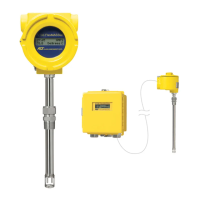
Figure 2-1. Model ST98 Insertion Flow Element Showing Orientation ..............................................2 - 2
Figure 2-2. Model ST98 In-Line Butt Weld Mount ..............................................................................2 - 4
Figure 2-3. Circuit Board Placement.....................................................................................................2 - 6
Figure 2-4. Customer Connection Board...............................................................................................2 - 6
Figure 2-5. Remote Wiring Diagram ....................................................................................................2 - 7
Figure 2-6. Optional Carbon Steel Enclosure .......................................................................................2 - 8
Figure 2-7. Wiring Diagram, DB-9 and DB-25 PC Connectors. .........................................................2 - 9
Figure 2-8. Remote Bracket Installation ...............................................................................................2 - 10
Figure 3-1. Menu Selections Chart........................................................................................................3 - 2
Figure 5-1. Component Identification ...................................................................................................5 - 5
Figure 5-2. TS2 Connector Plug............................................................................................................5 - 5
Figure 5-3. Terminal Block In Local Enclosure ...................................................................................5 - 5
Figure 5-4. Decade Box Connections ....................................................................................................5 - 8
Figure A-1. Local Enclosure, NEMA Type 4X and Hazardous Location ............................................A - 1
Figure A-2. Remote Aluminum Double Ended Enclosure NEMA 4X and Hazardous Location ........A - 1
Figure A-3. Remote or Local Enclosure, Carbon Steel NEMA Type 4X, and Div 2...........................A - 2
Figure A-4. 3/4 Inch Ferrule NPT Process Connection ........................................................................A - 3
Figure A-5. 3/4 Inch Ferrule NPT With Flange Process Connection...................................................A - 3