Operation, Maintenance, and Service
Preliminary Steps
2
2-3
Preliminary Steps
The Analyzer measures electrical parameters, as described below. These
voltages and currents are a natural phenomenon, and their presence within
reasonable limits does not constitute a hazard. However, it is necessary to
measure their values to determine if there is a significant change from previous
measurements or from the device specifications.
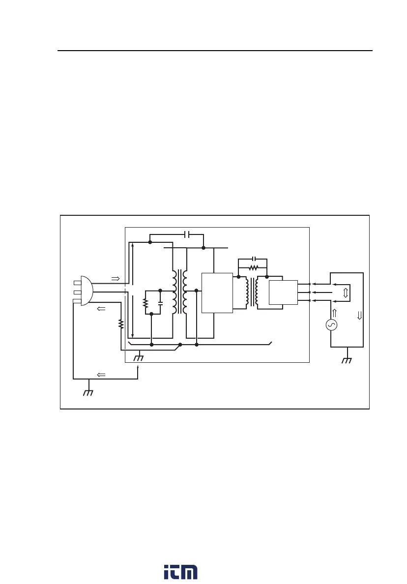
Figure 2-1 is a block diagram of a typical line-operated instrument with patient
connections. All measured parameters are labeled, and the following topics are
keyed to the labels in the diagram.
Hot
Neutral
Ground
Earth
Enclosure
Chassis
120/220
VAC
Grounded
Data and
Control
Circuits
Isolated
Patient
Circuits
I
E
I
L
Z
I
R
G
R
L
V
L
C
L
C
L
Z
L
I
C
I
A
I
I
I
P
fat02.eps
Figure 2-1. Block Diagram of a Typical DUT
Preparing the Analyzer for Use
WX Warning
To avoid possible electric shock, burning of the skin, or
personal injury to the patient, disconnect all patient
connections to the device before starting the following
procedure.
www. .com
information@itm.com1.800.561.8187
 Loading...