180
Users Guide
2-10
(5.5 X 5.5 in) piece of aluminum foil taped to the surface and the cable
clipped to the foil.
3. To make the measurement, place the FUNCTION switch in the
CHASSIS position and read the display in microamperes.
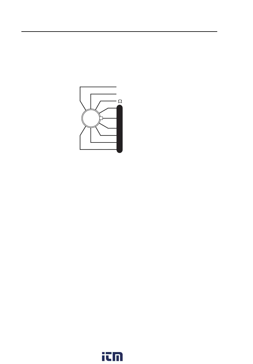
VV
AA
µAµA
L
E
A
K
A
G
E
- CURRENT- CURRENT
- RESISTANCE- RESISTANCE
- GROUND- GROUND
- CHASSIS- CHASSIS
- LEAD -GND- LEAD -GND
- LEAD -LEAD- LEAD -LEAD
- LEAD ISO- LEAD ISO
- DUAL- DUAL
- LINE VOLTS- LINE VOLTS
- CURRENT- CURRENT
- RESISTANCE- RESISTANCE
- GROUND- GROUND
- CHASSIS- CHASSIS
- LEAD -GND- LEAD -GND
- LEAD -LEAD- LEAD -LEAD
- LEAD ISO- LEAD ISO
- DUAL- DUAL
fat07.eps
4. Make measurements under all combinations of the OUTLET switch,
NORMAL and REVERSE; the GROUND switch CLOSED and OPEN;
the NEUTRAL switch CLOSED and OPEN; and with the device power
turned ON and OFF. Power to the outlet is OFF when the NEUTRAL
switch is in the OPEN position.
Note
Be sure to pause in the OFF (middle) position when switching the
OUTLET switch from the NORMAL to the REVERSE position.
Lead-to-Ground (Patient Source) Current
Lead-to-Ground [I
P
] (patient source) current would flow between an individual
patient lead and ground if the patient were to come into contact with earth
ground. An example is a patient with leads attached touching ground such as
an electric bed.
Note
Although originally required only for devices incorporating intra-
cardiac electrodes or conductive pathways directly to the heart, lead-
to-ground current has found its way into standards for all devices
having patient-applied parts.
www. .com
information@itm.com1.800.561.8187