Operation, Maintenance, and Service
Measuring Leakage Current
2
2-11
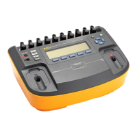
Use the following steps to measure lead-to-ground current:
1. Connect the patient leads to the corresponding snaps on the top of the
Analyzer. If the device has 10 leads, connect the limb leads and C1 (V1)
initially and repeat with C2 (V2) through C6 (V6). Lead nomenclature for
this test is not important.
2. Select LEAD-GND with the FUNCTION switch and read leakage current
in microamperes for any combination of the patient lead selected by the
LEAD switch.
VV
AA
µAµA
L
E
A
K
A
G
E
- CURRENT- CURRENT
- RESISTANCE- RESISTANCE
- GROUND- GROUND
- CHASSIS- CHASSIS
- LEAD -GND- LEAD -GND
- LEAD -LEAD- LEAD -LEAD
- LEAD ISO- LEAD ISO
- DUAL- DUAL
- LINE VOLTS- LINE VOLTS
- CURRENT- CURRENT
- RESISTANCE- RESISTANCE
- GROUND- GROUND
- CHASSIS- CHASSIS
- LEAD -GND- LEAD -GND
- LEAD -LEAD- LEAD -LEAD
- LEAD ISO- LEAD ISO
- DUAL- DUAL
fat08.eps
3. Make measurements under all combinations of the OUTLET switch,
NORMAL and REVERSE; the LIFT GROUND switch CLOSED and
OPEN; and the device power turned ON and OFF.
4. Rotate the LEAD switch to each lead to test individually and then to ALL
for testing with all leads connected together.
LEADLEAD
c
ra
ll
rlrl
lala
allall
fat17.eps
Current measured should be the same for all leads, including the ALL
position, as the current represents the isolation impedance to the patient
circuit.
www. .com
information@itm.com1.800.561.8187