Operation, Maintenance, and Service
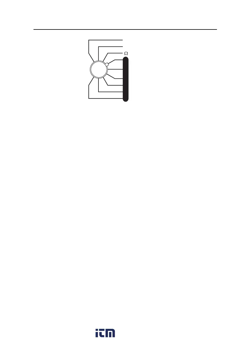
Measuring Leakage Current
2
2-9
VV
AA
µAµA
L
E
A
K
A
G
E
- CURRENT- CURRENT
- RESISTANCE- RESISTANCE
- GROUND- GROUND
- CHASSIS- CHASSIS
- LEAD -GND- LEAD -GND
- LEAD -LEAD- LEAD -LEAD
- LEAD ISO- LEAD ISO
- DUAL- DUAL
- LINE VOLTS- LINE VOLTS
- CURRENT- CURRENT
- RESISTANCE- RESISTANCE
- GROUND- GROUND
- CHASSIS- CHASSIS
- LEAD -GND- LEAD -GND
- LEAD -LEAD- LEAD -LEAD
- LEAD ISO- LEAD ISO
- DUAL- DUAL
fat06.eps
2. Make measurements under all combinations of the OUTLET switch,
NORMAL and REVERSE; the NEUTRAL switch CLOSED and
OPEN; and with the device power turned ON and OFF. Power to the
outlet is OFF when the NEUTRAL switch is in the OPEN position.
Note
Be sure to pause in the OFF (middle) position when switching the
OUTLET switch from the NORMAL to the REVERSE position.
Chassis (Enclosure) Leakage Current
Chassis [Enclosure] Leakage Current [I
C
] flows between the accessible
conductive chassis or enclosure and earth (ground) measured through a
1,000 Ω impedance.
The Analyzer measures chassis leakage from the exposed metal part on the
DUT, through the black cable and the AAMI load, back to the ground.
Use the following steps to measure chassis leakage current:
1. Connect the standard cable (supplied with unit) that has a black cable with
the clamp that has black insulation to the CHASSIS connector on the
front of the Analyzer.
2. Clamp the clip on the cable in turn to accessible conductive sections of the
chassis and the enclosure. Metal labels or incidental conductive hardware
are not applicable for this test.
If a non-conducting enclosure is used, present standards require
connection to the enclosure via a 200 cm² conductive foil in intimate
contact with the enclosure. This can be accomplished with a 14 X 14 cm
www. .com
information@itm.com1.800.561.8187