39/41B
Service Manual
1-4
Chapter 7. Schematic Diagrams
Chapter 7 contains the schematic diagrams for all assemblies and a list of mnemonic
definitions to aid in identifying signal name abbreviations.
1-3. Conventions
The following conventions are used in this manual:
• Printed Circuit Assembly (PCA)
A “pca” is a printed circuit board and its attached parts.
• Circuit Nodes
A pin or connection on a component is specified by a dash (-) and number following the
component reference designator. For example, pin 19 of U30 would be U30-19.
• User Notation
Switch positions used in the meter circuit descriptions correspond to those in the
schematic diagrams in Chapter 7.
1-4. General Information
1-5. Description
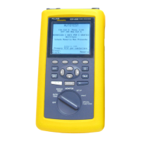
The Fluke 39 and 41B are handheld Testers used to measure voltage and current at
power line and harmonic frequencies. Using these inputs, the Tester automatically
calculates power and a wide range of other measurements useful in determining
harmonic distortion levels and sources.
These capabilities allow you to monitor power quality before and after an installation,
troubleshoot a power distribution system, and (with Model 41B) print out or download
data for additional analysis.
The Tester is both a harmonics measurement tool and a power meter or digital
multimeter. You can use the Tester to measure voltage events (undervoltage,
overvoltage, line outages, and neutral to ground levels), current levels, or to measure
power levels. Fundamental frequency measurements (to 100 Hz) and harmonic
frequency measurements (to about 2 kHz) are also possible.
1-6. Power Requirements
The Tester uses 4 Alkaline “C” Cells (ANSI/NEDA-14A, IEC-LR14) for primary power.
New Alkaline “C” Cells will provide a minimum of 24 hours of continuous operation
(typically 48 hours). You can also use NiCad batteries; however, depending on battery
condition, fully charged NiCad batteries provide 8 hours or less of continuous operation.
1-7. Options, Accessories and Related Equipment
The following accessories are supplied with the Fluke 39 and 41B:
• 80i-500s AC Current Probe
• TL-24 Test Leads (Set of two, Red and Black)
• TP-20 Test Probes (2)
• AC-20 Test Clips (2)