Maximum Conductor Size:
One 30 mm (1.18 in.), 750 kcmils (MCM) THHN, two 25 mm
(0.98 in.), 500 kcmils (MCM) THHN, or one 63 x 5 mm (2.5 x 0.2
in.) Bus Bar.
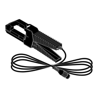
Output Cable: 1.6 meters (63 in.), BNC termination. Cable and
BNC are rated to 600V ac rms for enhanced safety.
Mechanical Shock: 100G per IEC 68-2-27
INSTRUMENT COMPATIBILITY
The 80i-500s is compatible with any oscilloscope, voltmeter, or
other voltage measuring device that has the following features:
• Accepts a standard BNC connector. A BNC-to-bannana
adapter (order PM 9053 from Fluke) can also be used with
standard inputs on a digital multimeter (DMM).
• Range and resolution capable of displaying 1mV of output
per amp of measured current.
• AC Volts accuracy of 1% or better to take full advantage of
the accuracy of the probe.
• Input impedance of greater than or equal to 1MΩ in parallel
with a maximum of 47 pF.
OPERATING INSTRUCTIONS (Scope Mode)
1. Connect the 80i-500s Current Probe to the desired input
channel on the oscilloscope.
2. Use a 1 : 1 probe setting.
3. Clamp the current probe around the conductor.
4. Press S. to select Scope Mode.
5. Press A.
6. Adjust V or v (volts/division) for the best vertical display.
(For line power currents less than 100A, 50 mV/div is a good
first choice.)
7. Adjust t (time/division) for the best horizontal display.
(For power line frequency, 5 msec/div is a good choice.)
OPERATING INSTRUCTIONS (Meter Mode)
1. See Figure 3. Connect the 80I-500s Current probe to
Channel A.
2. Use a 1 : 1 probe setting.
3. Clamp the current probe around the conductor.
4. Press Mto select the Meter Mode.
5. Press u or d to select an appropriate meter range.
(The current probe output is 1 mV per ampere measured.)
MEASUREMENT CONSIDERATIONS
Observe the following guidelines for positioning the current probe
jaws:
• Center the conductor inside the probe jaws.
• Make sure the probe is perpendicular to the conductor.
• If possible, avoid measurements close to other current
carrying conductors.