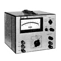
845A
2-11..
MECHANICAL
ZEROING
2-12.
It may be necessary to adjust the mechanical
zero control
of
the
Model
845
at more
frequent intervals
than
complete calibration. To mechanically zero the
instrument
proceed as follows:
a. Place
the
RANGE switch to 1000 VOLTS and the
POWER switch
to ON
or
to
LINE
OPR.
b.
Adjust
the mechanical zero adjustment screw
for
zero meter deflection.
c. Place the
RANGE
switch
to
10
MICROVOLTS
and
electrically zero
the instrument
as
outlined in para-
graph
2-5.
d.
Repeat
steps
a through c until the meter
is
me-
chanically
and
electrically
zeroed.
2-13,
OPERATION
AS A HIGH
IMPEDANCE
VOLTMETER
2-14.
To operate the
Model
845
as a
High
Impedance
Voltmeter,
perform the preliminary operations ac-
cording
to paragraph
2-5
and
proceed
as follows:
a.
Place
the controls as follows:
POWER
ON/LINE OPR or
BAT OPR
OPR
OPR
RANGE
1000
VOLTS
When
measuring voltages
in
the
microvolt
ranges, use copper wire having low thermal
EMF’s.
b. Connect the
voltage to be measured to
the
Model
845
INPUT terminal
and connect
the
common point
of
the
voltage being
measured to the Model 845 COM-
MON
terminal.
c. Deflection
of
the
meter indicates the polarity and
magnitude
of the
measured voltage. Increase
the
sensitivity
of
the
Model
845
for maximum on-scale
deflection.
2-15
OPERATION
AS A NULL DETECTOR
2-16.
The Model 845
may be used to monitor small
voltage
differences in bridge
circuits,
potentiometers,
and other
measuring
apparatus. In most
of
these appli-
cations
the
circuits are
adjusted
for
zero
deflection or
a null
on the Model 845. Equipment connections for
various
types of null detector
configurations are
illus-
trated
by Figure
2-2
through 2-4.
To operate the Model
845
as
a Null
Detector
perform the preliminary
oper-
ations
according
to paragraph
2-5
and
proceed
as
follows:
a. Select the
desired
equipment
application
as illus-
trated
by
Figure
2-2
through
2-4
and
make
the
appropriate
equipment
connections.
b. Place the
Model
845
controls
as
follows:
POWER
ON/LINE
OPR or
BAT OPR
OPR
OPR
RANGE
as desired
c.
Adjust the circuit being
measured for
zero
or
a null
deflection on the
Model
845
meter.
Figure
2-2.
BRIDGE
DETECTOR-FLOATING
SUPPLY
2-3

 Loading...