84 5
A
Figure
2-4.
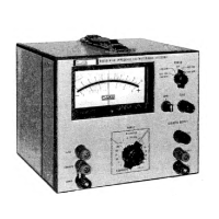
BRIDGE DETECTOR-FLOATING
NULL
DETECTOR
2-19.
USE
OF
ISOLATED
OUTPUT
2-20. DC
ISOLATION
AMPLIFIER
2-21,
The
Model
845 may be
used as a dc
isolation
amplifier
havii^
a
vdtage
gain csf ip
to
120 db,
dependii^
on
the
settings of
the
RANGE
switch
and the
OUTPUT
LEVEL
control. To
compute
the
maximum voltage
gain
on any
range of
the Model
845,
iise
the following
formula:
1
volt
(maximum
isolated
output)
voltage
gain to db
.
20 log
ranGE (in volts)
2-22,
RECORDER
OUTPUT
2-23.
The Model 845
ISOLATED OUTPUT may be used
to
provide
an output voltage,
adjustable from zero
to
one volt for a
full-scale
meter deflection for
use
with
a
recorder. Since the
output is
isolated from the input,
floating
measurments can be made
without
the
use
of a
floating
recorder.
To
use
the
adjustable
recorder
out-
put,
proceed
as
follows:
2-17. MEASURING
VOLTAGES
WITH
A
STANDARD
CELL
2-18.
The Model 845
may
be
used
with a voltage
di-
vider and a
standard
cell
to calculate unknown voltages
with
a high degree of accuracy.
Connect
the
equipment
as illustrated in Figure
2-5.
Perform the
preliminary
operation as
outlined
in
paragraph
2-5
and proceed as
follows:
a. Place
the
Model
845
controls
as
follows:
POWER
ON/LME OPR or
BAT OPR
OPR OPR
RANGE
as desired
b. Adjust the voltage divider for zero or null
deflection
on
the Model 845
meter while
placing the RANGE
switch
to successively more sensitive
ranges.
c. Calculate the
unknown voltage
by dividing the
stand-
ard cell voltage
by
the
final
division ratio
of
the
divider.
2-4
a.
Connect the recorder to
the ISOLATED
OUTPUT
terminals.
The lower ISOLATED
OUTPUT
terminal
is
connected to
chassis
ground. K a ground
reference
is
undesirable, disconnect the
green wire
between
the
power
supply cir-
cuit board and the grounding pin on the
ac
line plug. Refer
to
F%ure
2-6
for wire
location.

 Loading...