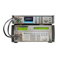
Reference Multimeter and 8 ½ Digit Multimeter
Front and Rear Panel
15
Table 4. Rear-Panel Features (cont.)
Number Name Function
I Fuse holder
Holds the fuse that is in series with the rear Input A Hi input. F1.6AH
250 V fuse protects the current-measuring circuity when using the
rear terminals for signal input.
J GROUND
Five-way binding post connected to earth ground through the earth
ground connector on the mains plug.
K GUARD
This five-way binding post in the External Guard OFF state is isolated
from any internal connections, and the internal guard shields are
connected to the internal 0 V. In the External Guard ON state, the
internal guard shields are disconnected from the internal 0 V and
connected to the GUARD terminal of the selected front or rear input.
In the Ohms or PRT functions, the Ext. Guard ON selection is
modified to provide an Ohms Guard. Guarding is explained
throughout this manual.
L
FREQ COUNTER
IN
This is a 50 Ω impedance input to the frequency counter function.
See Frequency Counter. Measure a frequency input from the Volt
INPUT HI-LO terminals, or through this BNC connector.
M FREQ REF IN
A reference 10 MHz signal can be applied to this BNC connector to
provide the Product with an external frequency reference. Intended
to be used in a system where several devices are phase locked to a
common reference and can reduce trigger latency.
N
USB Type A
connector
USB port to allow transfer of the Product’s readings to a USB
memory stick. This port is capable of providing 5 V at 0.5 A
maximum, and supports an external keyboard (but not a mouse).
See Memory Setup.
O
USB Type B
connector
USB port for port for remote control of the Product. See USB
Interface. See the Remote Programmer’s Manual.
P LAN connector
10/100/1000 Base/T Ethernet connector for remote control of the
Product. Remote Interface Setup in the Remote Programmer’s
Manual describes proper cabling, how to set up the interface, and
how to transmit data from the Product. Remote Interface Setup also
describes how to use the Ethernet interface for remote control. See
the Remote Programmer’s Manual.
Q
IEEE-488
connector
A standard GPIB interface connector to operate the Product in
remote control as a Talker or Listener on the IEEE-488 Bus. See
Remote Interface Setup for bus connection. See the Remote
Programmer’s Manual for remote programming instructions.
R AC mains fuse
The T1.25AH 250V mains fuses are accessible after removing the
mains power cord. See Maintenance.

 Loading...