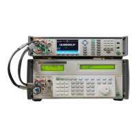
Reference Multimeter and 8 ½ Digit Multimeter
Features
81
Use the navigation keys and select the appropriate behavior for the TRIG OUT
signal. See Figure 25 for a detailed explanation.
Table 17. Output Behavior Choices
Trigger Out Reading Event Description Typical Usage
Signal Acquired
1 μs output pulse occurs at the
end of the signal acquisition (a/d
integration period), before the
reading is actually complete.
Push (Polarity) to select a
Pos (high) or Neg (low ) pulse.
See Figure 25.
Trigger an external scanner
to the next channel. If the
scanner is a slower, relay
type, this setting advances
the channel sooner than the
Reading Complete event
below.
Aperture open
Square wave output with a high
or low level during the signal
acquisition (integrate) period.
Push (Polarity) to select a
Pos (high) or Neg (low) level.
To minimize noise pickup
synchronizes external
equipment to only be active
when the Product A/D is not
acquiring a signal.
Reading counts complete
1 μs output pulse occurs after a
specified number of readings is
completed. Push
(Polarity) to select a Pos (high)
or Neg (low ) pulse.
The number of readings is
determined by the Count
parameter in Trigger Setup. See
Triggering Measurements.
Synchronize an external
scanner to the Product when
making multiple readings
per scanner channel.
On Event (new)
1 μs output pulse occurs when a
Limit is exceeded. Limits are set
in the Analyze function.
Advance an external
scanner to the next channel
when a voltage set by the
Limit Math function is
exceeded.
Reading complete
1 μs output pulse occurs after
each reading for any
measurement function. For ACV
and ACI, which are sampled
measurements, a pulse is output
after each computed reading, not
after each sample in the
measurement process. Push
(Polarity) to select a Pos
(high) or Neg (low ) pulse.
Synchronize an external
scanner to the Product when
making one reading per
scanner channel.

 Loading...