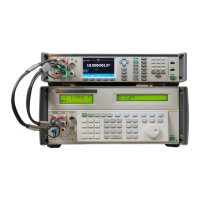
Reference Multimeter / 8½ Digit Multimeter
Calibration Interval and Performance
3
Alternate equipment may be used, but users should ensure it provides adequate calibration
uncertainties. Performance of the Product after calibration should be determined by combining the
applicable calibration uncertainties provided by the calibration equipment with the 8508A Relative to
Standards specifications. (Fluke Calibration recommends RSS summation).
Calibration Adjustment Overview
The Product has two sets of stores: Certified and Baseline. Only the Certified stores can be changed
during adjustment. Store is populated at manufacture and would not normally be overwritten. The
Baseline store provides a facility to monitor the long-term performance of the Product independent of
regular adjustment.
Calibration of all functions of the Multimeter is done from the front panel or remotely. No hardware
adjustments are necessary.
Manual Adjustment
The Product guides you though the manual adjustment process. Some early steps in the process are
only required after the Product is repaired.
The adjustments are numbered in groups:
001 After first build or post repair
101 One-time factory characterizations
201 Voltage
301 Current
401 Resistance
501 Capacitance (not applicable to 8558A)
601 Frequency
701 Zero
The full list of adjustment points and required inputs is in Table 2. Routine adjustment starts at Step
201: ADC Reference Characterize.
Equipment Name Recommended Models Comment
1 GΩ Standard Resistor Fluke Calibration 8508A-7000K
1 GΩ Standard, Low
thermal emf leads, two 4-
wire shorting PCB
100 MΩ Standard Resistor
1 Ω Standard Resistor Fluke 742-1
1 nF Standard Capacitor
8588A adjustment only
(not required for 8558A
adjustment)
10 MHz Reference Off-air standard
4-wire short PCB
Table 1. Equipment for Calibration Adjustments and Performance Verification (cont.)

 Loading...