110/113/114/115/116/117
Calibration Information
10
Set calibrator to standby, reconfigure leads, and program for amps output
31.
DC Amps
10.00 A 10 A NA
9.87 to
10.13
NA
9.87 to
10.13
32.
AC Amps
6.000 A 5.0 A, 45 Hz NA
4.922 to
5.078
NA
4.922 to
5.078
33.
$
DC μAmps
600.0
μA 600 μADC NA
593.8 to
606.2
NA
34.
$
DC μAmps
600.0
μA 600 μAAC, 45 HZ NA
590.7 to
609.3
NA
35.
y
Temperature
--- Open input NA
0PEn
NA
36.
--- 0.0 °C NA -1.0 to 1.0 NA
37.
--- 400 °CNA
395.0 to
405.0
NA
38.
AUTO-V
LoZ
--- 0.5 V, 45 Hz NA
0.2 to 0.8,
AC
Annunciator
On
NA
0.2 to 0.8,
AC
Annunciator
On
0.2 to 0.8,
AC
Annunciator
On
39.
--- 0.5 v, 0 Hz NA
0.2 to 0.8,
AC
Annunciator
On
NA
0.2 to 0.8,
AC
Annunciator
On
0.2 to 0.8,
AC
Annunciator
On
40.
--- 500 V
[2]
, 500 Hz NA
489.7 to
510.3
NA
489.7 to
510.3
489.7 to
510.3
41.
VoltAlert
Hi
--- NA [3]
42.
VoltAlert
Lo
--- NA [4]
[1] If using a Fluke 9100 calibrator, the Calibrator Frequency mode must be used to obtain accurate frequency.
[2] To keep from tripping the calibrator to standby, ramp up the voltage in 50 V increments with a 5 second delay between increments.
[3] See steps 1-5 in Testing the VoltAlert Function (117 only).
[4] See steps 6-9 in Testing the VoltAlert Function (117 only).
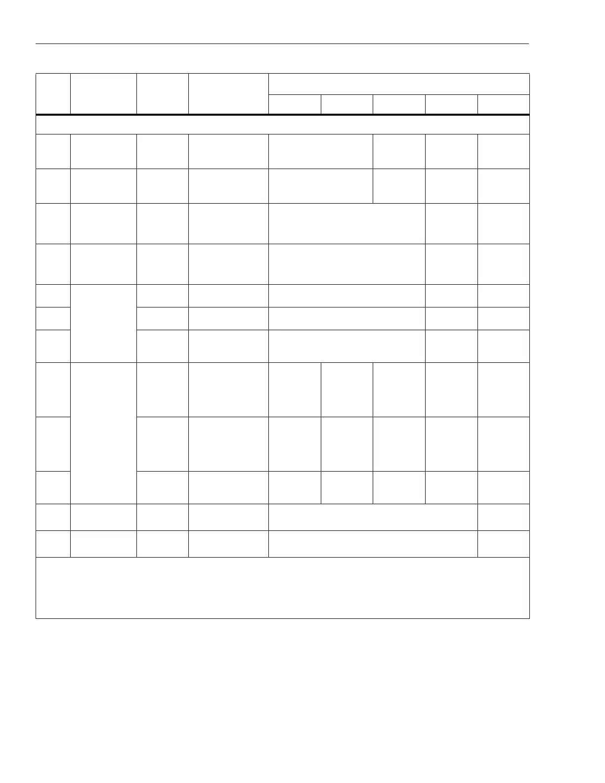
Table 3. DMM Performance Tests: 110/114/115/116/117 (cont.)
Step Function Range Applied
Display Reading
[1]
110 114 115 116 117
 Loading...