19
Connecting the OptiView XG to a Network
Caution
To prevent equipment damage, do not connect the OptiView XG Port A or Port B to a telephone
line or an ISDN line.
Link Speed and Utilization Indicators
There are two link status indicators for each network port: Link Speed (on the left) and Utilization
(on the right).
Installing/Removing the SFP or SFP+ Fiber Adapter (Transceiver)
To install an SFP or SFP+ Fiber adapter, remove the protective cap from the adapter and slide the
adapter into Port C or Port D. To remove, gently pull the SFP’s bail. If the SFP has retention tabs,
press and hold the tabs on the sides of the adapter and pull it from the fiber port.
A list of supported SFP and SFP+ modules is given in the specifications on page 54. See
www.flukenetworks.com for a complete list of supported SFP and SFP+ modules.
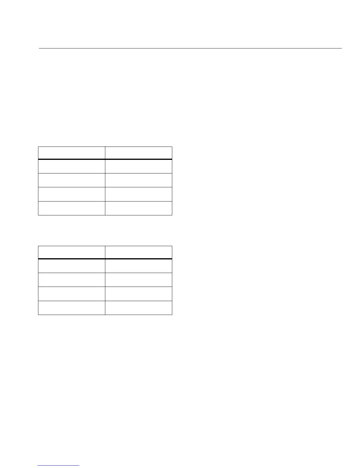
Table 4. Network Port Link Speed Indicator
Color Link Speed
Green 10 Mbps
Blue 100 Mbps
White 1000 Mbps
Magenta 10 Gbps
Table 5. Network Port Link Utilization Indicator
Color Link Utilization
Flashing Green 0% - 9%
Green 10% - 50%
Yellow 51% - 80%
Red 81% - 100%
 Loading...