18
OptiView XG Network Analysis Tablet
Getting Started Guide
Connecting the OptiView XG to a Network
You can connect the OptiView XG to a network via network ports A, B, C, or D, or via the built-in
wireless adapters.
The OptiView XG’s management port can be used for remote control of the analyzer (from a
separate network). This lets you control the analyzer from a management network while using
the OptiView XG to test a production network.
Establishing a Wired or Fiber Connection
Connect an appropriate cable from one of the OptiView XG’s network ports to the network that
you want to test. The OptiView XG will find the active network interface and obtain an IP address.
Then it will begin discovering the network.
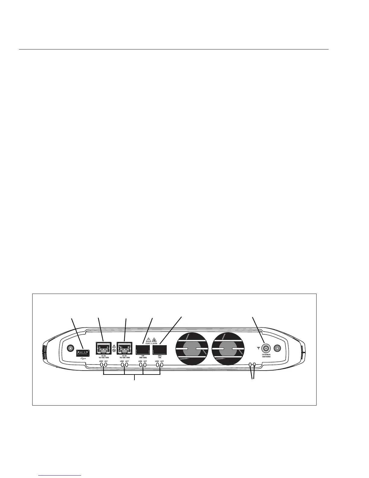
Network Ports
The OptiView XG has the following network ports:
• Port A: RJ45 Ethernet connector, 10/100/1000 Mbps
• Port B: RJ45 Ethernet connector, 10/100/1000 Mbps
• Port C: 100/1000 Mbps Ethernet over fiber on standard SFP socket
• Port D: 10 Gbps Ethernet over fiber on standard SFP+ socket
• Management Port: RJ45 Ethernet connector, 10/100/1000 Mbps
GLZ02.EPS
Figure 12. OptiView XG Network Ports
<View of network connectors>
Port A Port B Port C Port DUSB Port External Antenna Connector
Link Speed and Utilization Indicators Wi-Fi Status Indicators
 Loading...