D - 2 Users Manual
This set-up will cause no problem as CH 1 supplies a constant current (CC) of 5A
and CH 2 supplies the additional current needed in constant volta
e mode (CV
indicator).
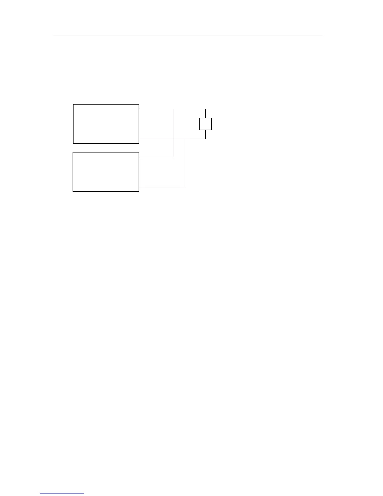
A problem will arise when the current needed by the load decreases below 5A, for
example when the load resistance increases. This is illustrated by fi
ure D.2 Channels connected in parallel to a load. Both channels are in
Constant Volta
e mode.
CH 1 will now enter the Constant Volta
e (CV) mode, as the current needed by
the load is less than Iset (5A). This implies that the volta
e across the load will
chan
hest Vset (12V). As Vset of CH 2 is 10V, its down pro
rammer
will become active, so that CH 1 will supply 3A plus the current the down
pro
rammer of CH 2 will sink. So this set-up is not suitable for load currents, which
can be lower than Iset of the Constant Current channel.
For this case there are two solutions. You can set the current of CH 1 to a value
below 3A so that CH 1 will enter the Constant Current mode as indicated in
Fi
ure D.1. Or, you can set both channels to the same volta
e, so that there will
be a constant volta
e across the load. When the volta
es are exactly equal, the
down pro
rammer will not become active and the current throu
h the load will be
equal to the sum of the currents of the individual channels.
Be careful in usin
the Standby and Disable modes
Consider the followin
case. You have connected two channels in parallel. You
don't need the second channel to supply current, because the first channel can
supply enou
h current. You disable the second channel to switch it off. The down
pro
rammer of this channel will try to sink its output to 0V. As the first channel still
supplies a volta
rammer of the second channel will continuously
sink current. This causes power dissipation inside the case, which must be
prevented as the Power Supply is not desi
ned for this use.
Vset = 12V
Iset = 5A
4Ω
12V
3A
CC
3.5A
12V
CH1
Vset = 10V
Iset = 5A
CV
-0.5A
12V
CH2