EasyManua.ls Logo

Fluke PM2813 - Page 58

Fluke PM2813
115 pages
Print Icon
To Next Page IconTo Next Page
To Previous Page IconTo Previous Page
Loading...
5 - 6 Users Manual
The followin
g
illustrations show the possible connections.
SERIES connection to increase the total output volta
g
e capability:
WARNING: To
g
uarantee the safe use of the power supply, the total
maximum volta
g
e at each terminal must not exceed 240V
with respect to
g
round.
Examples: • 2x 60V/2A = 120V/2A : maximum power = 240W
• 2x 120V/1A= 240V/1A : maximum power = 240W
• 2x 8V/15A = 16V/15A :maximum power = 240W
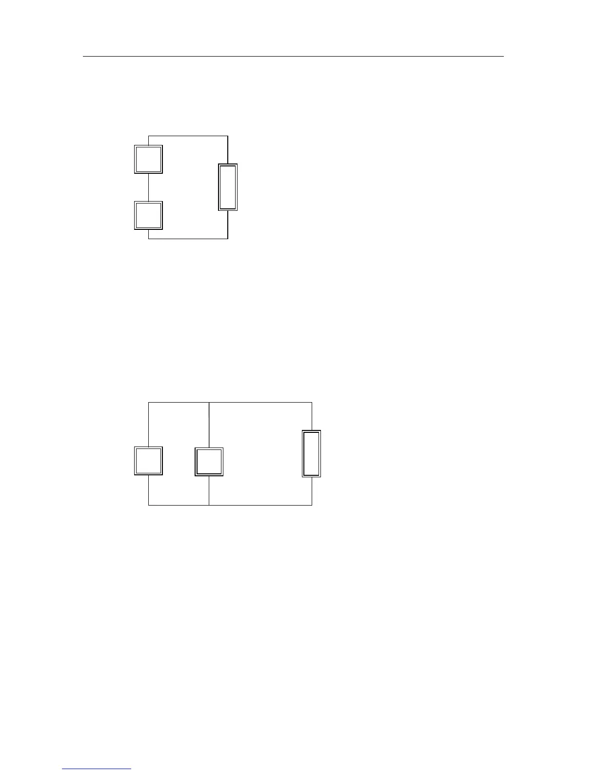
PARALLEL connection to increase the total output current capability:
Examples: • 2x 60V/2A = 60V/4A : maximum power = 240W
• 2x 120V/1 = 120V/2A : maximum power = 240W
• 2x 8V/15A =8V/30A : maximum power= 240W
CAUTION: Only output channels with equivalent volta
g
e and current
ratin
g
s may be connected in series or in parallel to prevent that
the channel with the lowest ratin
g
s will be dama
g
ed.
V
1
V
2
L
O
A
D
I
load
= V
load
/
R
load
+
+
P
load
= V
load
x I
load
+
-
V
load
=V
1
+ V
2
I
load
= I
1
+ I
2
V
load
=I
load
x
R
load
P
load
=I
load
x V
load
V
1
V
2
L
O
A
D
+
+
I
1
I
2
+
-

Table of Contents

Related product manuals