used
to be
able to use all 128K bytes. The
signal from U6
pin 21 and 22
controis that one quarter of the
memory is
used for the
moment. At reset the first quarter
is
seiected
(U6 pin 21
and
22
goes high).
To be able
to
make a CRC-check of the
contents
of the
PROM,
the micro controlier must be
able
to read the con-
tents of the PROM
as
data.
The address
and data bus ADO to ADI 5 can
be separated
into
two parts. By removing resistors
R183 to R190, R209
to
R212, and R221 to R224 you can
separate
the micro
controiler, the
address
latch and the PROM from
all
other
circuits
on the bus. By removing R225 to R232
you can se-
parate the counter
circuits
and
the
GPiB controller
from the
AD-bus.
The micro
controiier communicates with the
outer
worid by
I/O circuits
connected
to the address and data
bus
ADO
-
ADI
5, The WR (pin
40)
and RD (pin
61)
signais from U6
controi the direction
of information.
These two signais,
with
the address
decoding iogic, produce "chip select"
signals
for the I/O circuits.
The
address decoding iogic uses
the
A5
-
A15 to
produce chip seiect signals. Chip
select
si-
gnais are
generated for:
-
PROM,
U16 and U17, and RAM, U9 to
U13.
“
The input
amplifier
relay
driver
U18, display
scanning
cir-
cuit U19 and U20,
and the GPIB driver U78.
“
The trigger level
circuits U63, U64, and U60
and
the
counter circuits U56
and U58.
To show
that
the counter measures, a gate
indicator
is pla-
ced on the
front
panel, it is controlled from the
micro
con-
troller U6 pin 28
via
V54.
The blinking of the LED
is
softwa-
re controlled, and
does not necessarily
reflect the true sta-
te
of the measuring hardware.
The
RAM, U13 has battery backup. If the
counter
is ON or
in STAND-BY,
the
+12VREG gives power to the
RAM pin
28,
via U7 and D30
to
get
+5
V. If the counter is not
con-
nected to the line
power
at
all,
the
3
V
battery gives
power
to the
RAM. The Schottky diode D31
isolates
the battery
and preserves
power when +12VREG
is present.
When
this happens pin
27 of the
RAM is low, and the RAM
goes
to the power-down mode.
At this
point the RAM needs a
2 V
supply voltage.
The version of the main PCA are
identified
by the resistors
R524 and R525. This DC voltage
are fed into the analog
in-
put ACHO of the
p-controller
U6,
which
recognizes the bo-
ard. This makes it
possible
to make the software backward
compatible.
The different prescalers
are
identified
in a similar way.
R1 92 to R1
94
and
R203 to R204 forms a resistor
network
that
generates
different DC voltages at the
ACH1
input of
the p-controller. This DC voltage
depends
of how the pins
12, 14,
and 16 on P20
are connected to ground and
+5
V
on the
prescaiers.
•
Reset
Circuit
A special reset circuit is
included
in
the
design. U8 is a
spe-
cial supply supervisor,
if the
+5
V
becomes lower than
4.5 V, the reset
output
pin
4
goes low. This gives
a micro
controller reset.
For test
purposes the micro
controller
can
be forced
to
reset
by short circuiting the pads J10.
The
length of the reset pulse is set by C310;
2.2
pF gives a
pul-
se of approximately 40 ms. The supervisor circuit also con-
trols
the reset pulse during the power-on, so the micro con-
troller
starts in a controlled manner.
•
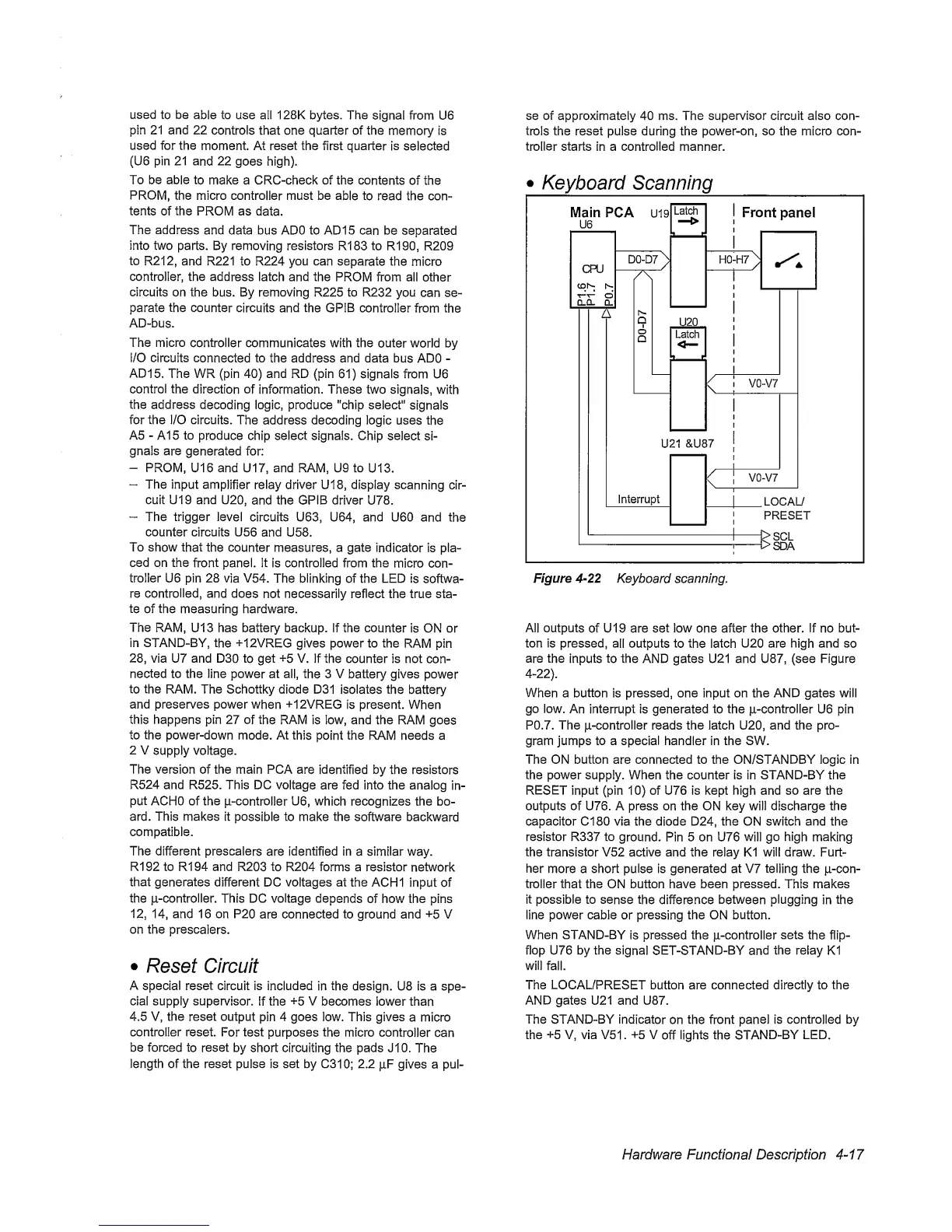
Keyboard Scanning
Figure
4-22
Keyboard scanning.
All outputs
of U19 are set low one after the other, if no but-
ton is pressed,
all outputs to
the
latch
U20
are high
and
so
are
the
inputs to the AND gates U21 and U87, (see Figure
4-22).
When
a button is pressed, one input on the AND gates will
go low.
An
interrupt
is generated to the |i-controller U6 pin
P0.7. The p-controller reads the latch U20, and the pro-
gram jumps to a special handler in the SW.
The ON button are connected to the ON/STANDBY logic in
the power supply. When the counter Is in STAND-BY the
RESET
input (pin
10)
of U76 is kept high and so are the
outputs of U76. A press
on
the ON key will discharge the
capacitor Cl 80 via the diode D24, the ON switch and the
resistor R337 to
ground. Pin 5 on U76
will
go high
making
the transistor V52 active and the relay K1 will draw. Furt-
her
more a short pulse is generated at V7 telling the p-con-
troller that the ON button have been pressed. This makes
it possible to sense
the
difference
between
plugging
in
the
line power cable or
pressing
the ON button.
When STAND-BY
is pressed the p-controller
sets
the flip-
flop U76 by the
signal SET-STAND-BY and
the relay
K1
will
fall.
The LOCAL/PRESET button are connected directly to the
AND gates U21 and U87.
The STAND-BY indicator
on
the
front
panel
is controlled by
the
+5
V, via V51 .
+5
V
off
lights
the
STAND-BY
LED.
Hardware Functional Description
4-17
 Loading...


