Measuring
Logic
(Functional
Level
7)
•
ASIC Stimuli
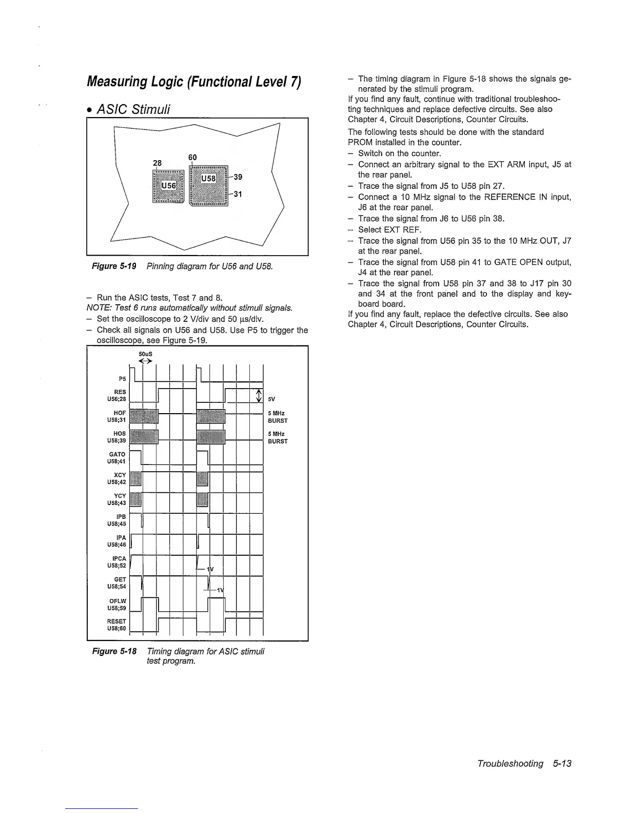
Figure
5-19
Pinning diagram
for
U56 and U58.
-
Run
the
ASIC tests, Test
7 and 8.
NOTE: Test
6
runs
automatically without stimuli signals.
-
Set the
oscilloscope
to 2 V/div and
50
|i,s/div.
-
Check all
signals on U56 and U58.
Use
P5
to
trigger the
oscilloscope,
see Figure
5-19.
-
The timing
diagram in Figure
5-18
shows
the
signals ge-
nerated by
the stimuli program.
If you find any fault, continue with traditional
troubleshoo-
ting techniques and replace defective circuits. See
also
Chapter
4,
Circuit
Descriptions,
Counter Circuits.
The following tests should be done with the
standard
PROM Installed
in
the
counter.
-
Switch on the counter.
-
Connect an arbitrary signal to the EXT ARM input, J5
at
the rear
panel.
-
Trace the signal from J5 to U58 pin 27.
-
Connect a 10 MHz signal to the REFERENCE IN
input,
J6 at the
rear
panel.
-
Trace the signal from J6 to U56 pin 38.
-
Select EXT
REF.
-
Trace the signal
from U56 pin
35 to the 10 MHz OUT, J7
at
the rear
panel.
-
Trace the
signal from U58 pin 41
to GATE OPEN output,
J4
at
the rear panel.
-
Trace
the
signal from U58 pin 37
and 38 to J17 pin 30
and
34 at the front panel and to the
display
and key-
board board.
If you find any fault, replace the defective circuits. See also
Chapter
4,
Circuit Descriptions, Counter Circuits.
Figure
5-18
Timing diagram
for
ASIC stimuli
test program.
Troubleshooting
5-13