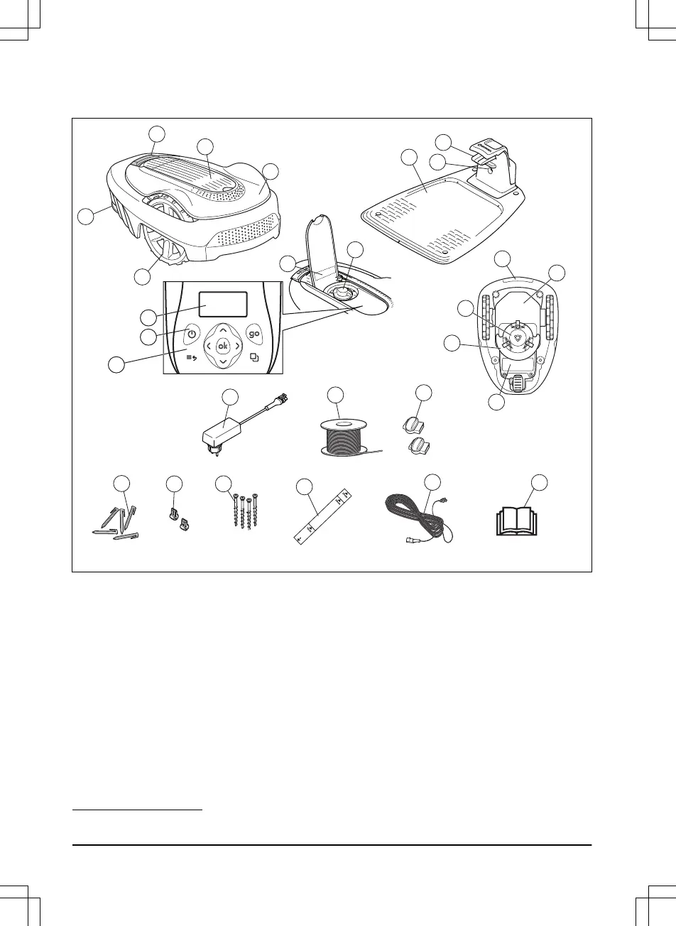
The numbers in the figure represent:
1. Body
2. Hatch to display, height adjustment and keypad
3. Stop button
4. Rear wheel
5. Front wheels
6. Charging station
7. Contact plates
8. LED for operation check of the charging station,
boundary wire and guide wire
9. Cutting height adjustment
10. Rating plate
11. Display
12. ON/OFF button
13. Keypad
14. Cutting system
15. Blade disc
16. Handle
17. Chassis box with electronics, battery and motors
18. Battery cover
19. Power supply
1
20. Loop wire for boundary loop and guide wire
21. Couplers for loop wire
22. Stakes
23. Connector for the loop wire
24. Screws for securing the charging station
25. Measurement gauge for help when installing the
boundary wire (broken loose from the box)
26. Low voltage cable
27. Operator’s Manual and Quick Guide
1
The appearance may differ depending on market.
4 - Introduction 1392 - 007 -