10
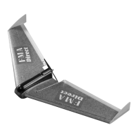
STEP 23: Locate the propeller and propeller adapter shaft, spinner
and set screws. Install the propeller onto the propeller adapter shaft
so that the propeller “pushes” air away from the back of the wing.
This will be backwards from the normal “puller” type installation
where the motor is mounted on the nose of the airplane. Verify
proper installation of the propeller by checking to see that any printed
information such as prop size or brand name is mounted on the side
of the prop away from the spinner. Install the spinner and hand
tighten using a hex wrench or small screwdriver shaft as a handle
through the hole in the spinner. Install the two set screws in the sides
of the propeller adapter shaft being careful not to cross thread.
STEP 22: Feed the servo wires up from the battery compartment,
through the battery hatch slots as in the illustration. Your finished
hatch/canopy assembly should appear as shown. The battery hatch
flips back to allow access to the battery. When the battery hatch is
closed, the canopy is free to flip back over the tray, capturing the
battery hatch and covering the flight pack and propulsion equipment.
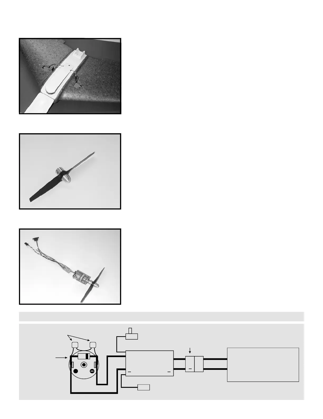
STEP 24: The motor pack that shipped with your ARF is made up of
the ESC, the motor, capacitors, Shottky barrier diode, and wiring, pre-
assembled and ready for installation. If you are not using an FMA
Direct motor pack, please refer to the diagram following this step for
proper connection of ESC / motor. Install propeller assembly to the
motor shaft. Press the assembly until it is within 1/16” to 1/8” of the
motor face. Tighten the two set screws using the proper hex wrench.
+
0.01UF MOTOR
CAPACITORS
SHOTTKY DIODE
CATHODE (BAND)
TO ESC + ALWAYS
ELECTRONIC
SPEED CONTROL
(ESC)
MTR
BATT
++
+
MALE
PLUG
RCVR
PLUG
ESC
POWER
SWITCH
POWER
PACK
BATTERY
RED
WIRE
BLACK
WIRE
MOTOR
MOTOR PACK CONNECTIONS
 Loading...