11
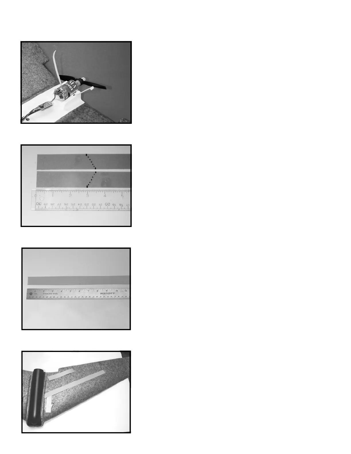
STEP 26: Locate two pieces of the 0.010” (thick) LEXAN
(TM)
tape. On
each piece of tape, mark one side at 3”; mark the other side at 3.5” as
illustrated. Cut each of the tapes across the equal but opposite
angles as in the illustration. You will end up with two short pieces of
tape to be used for holding the servos in place and two longer pieces
that will serve as the structural spars for the top sides of each wing
half.
STEP 25: Assemble the motor pack to the equipment tray as
illustrated. Feed the nylon tie through the holes you cut in the motor
mount. Pull the nylon tie tight so that the clamp is resting closest to
either hole and cut off the excess.
STEP 27: Steps 27 and 28 apply to 400 class kits only! If you do not
have a 400 class kit, please proceed to step 29. If you have a 400 class
kit, locate the four pieces of 0.010” LEXAN
(TM)
tape provided. Two of
these have been cut slightly shorter in STEP 26 above and are angled
on one end. Mark and cut off 6” from the square ends of all four
pieces of tape. The 6” pieces will provide added structural support to
the wing where the prop cutout is molded into the trailing edge of the
wing. The two shorter pieces with the angle cuts on one end will be
used for structural support for the top of the wing. The two longer
pieces will be used for structural support for the bottom of the wing
where the most stress occurs in flight during loops.
STEP 28: This illustration shows the placement of the structural and
servo tapes prepared in STEPS 26 and 27 for a 400 class kit. Do not
install the tapes at this time, but test the placement of each as
follows. The long tape should be positioned so that the end closest to
the fuselage begins where the wing joins the fuselage and is centered
over the servo wire slot. The end closest to the wing tip should be
centered on the wing panel. The servo tape should butt up against
the structural tape and center over the servo. The front of this tape
should extend 1” beyond the servo case (toward the leading edge). If
required, trim the angle cuts slightly. Put the short servo tapes aside
as these will not be installed until radio installation is complete!
400 CLASS ONLY
400 CLASS ONLY
 Loading...