3
Issue/Rev. 0.6 (2/06)
Installation (con’t)
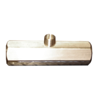
Electrical Installation (Figure 2)
Thread the magnetic pickup into the mounting boss
located on the top of the flowmeter. If the pickup does
not have wire leads included, connect the signal cable
to the pickup by threading on the keyed connector.
Note: Hand Tighten Only. Use of tools to tighten
the pickup can damage the flowmeter and pickup.
Turbine Meter Maintenance
Removal of Flowmeter Internals
Cartridge Type Sizes 3/4 Inch through 2” (Figure 3)
The cartridge type turbine flowmeter utilizes internals as-
sembled into a single part, eliminating the need for the three
part internals kit.
Note: This type of internals is not interchangeable with any
other body type.
1) Remove the magnetic pickup.
2) Identify the upstream end of the meter by locating
the two grooves visible from the outside of one end.
3) Remove the retaining ring from the end of the flow
meter identified by the grooves.
4) Slide the internals out of the flowmeter. It may be
necessary to push the internals out by gently applying
pressure to the opposite end.
5) Inspect the internal bore of the flowmeter for defects.
The internal surface of the flowmeter should be
smooth. If the surface is damaged, the flowmeter
body should be replaced.
6) Inspect the internals kit for damage or wear. If it ap-
pears to be damaged, replace it with a new
internals kit.
Replacement of Flowmeter Internals
Cartridge Type Sizes 3/4 Inch through 2 Inch
1) Identify the upstream end of the turbine flowmeter by
locating the two grooves visible from the outside of one
end.
2) Identify the upstream end of the turbine flowmeter inter-
nals by locating the end with a cone recessed between
two supports forming a “V”.
3) Insert the end opposite of the recessed cone into the
groooves located in the upstream end of the turbine flow
meter body.
4) Slide the flowmeter internals into the turbine flowmeter
body until it seats firmly against the downstream end.
5) Insert the retaining ring into the upstream end of the tur-
bine flowmeter, pushing it far enough into the flowmeter
body to engage the retaining ring slot directly above the
turbine flowmeter internals.
Figure 2
Figure 3

 Loading...