www.fmiproducts.com
56131J8
PRE-INSTALLATION PREPARATION
Continued
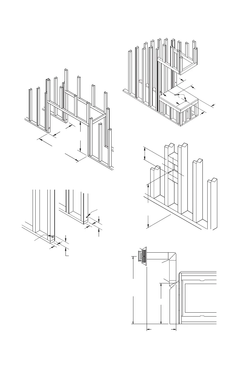
Figure 9 - Rough Opening for Installing
See-Thru Fireplace
3"
1" Dia. Hole
3"
2" Dia. Hole
1"
2"
Figure 10 - Hole Locations For Gas Line
and Electric Wires for Peninsula and
See-Thru Fireplaces
Height
Depends On
Installation
10"
Square Min.
Figure 12 - Rough Opening for Installing
Exterior Vent Terminal
Vertical
Height
Depends on
Installation
26
3
/
8
"
Horizontal
Length Depends
on Installation
90
o
Elbow
45
o
Elbow
Figure 13 - Vent Opening Height
Figure 11 - Alternate Gas Supply
Location
1 1
15
/
16
"
10
1
/
2
"
20
3
/
16
"
1
1
/
2
"
The gas supply line may be connected through
side framing or alternately through lower sub-
ooring or a platform base if provided (see
Figures 10 and 11). Depending on installation,
refer to appropriate illustrations.