14
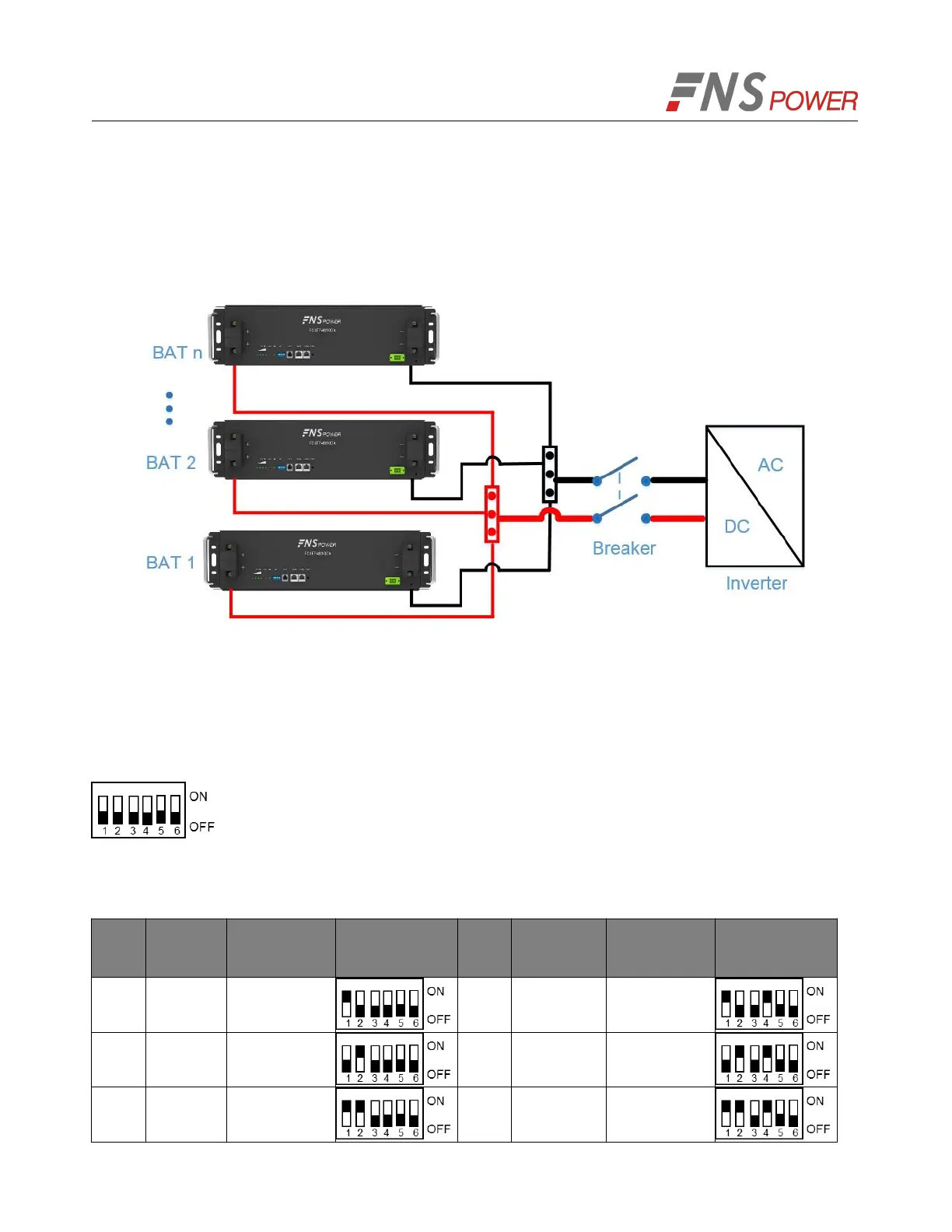
1. As shown in Figure 5-5, following the cable connection method of the single battery, connect the
positive and negative cables between the Battery 1 and the busbar, Battery 2 and the busbar, and
Battery N and the busbar respectively.
Note: To ensure the current balance, please use cables with the same diameter and length for each
battery.
Figure 5-4: Multiple Batteries Connections
2. As shown in Figure 5-7, connect the communication line (a standard RJ45 network cable) between
the adjacent batteries.
3. When performing multi-machine parallel communication operation, it need to configure the dialing
address of each battery. The dialing code is in BCD format, and the address 0 is defined as
. The dialing address configuration of each battery is shown in Table 5-1.
According to the number of the battery in parallel, set the dialing address of the corresponding battery.
Table 5-1: The Dialing Address Configuration of Each Battery
 Loading...