VENTILATION (continued)
Ventilation fitted under, or within immediate vicinity of the appliance must not be used as it may adversely effect
performance of the ODS system. For Republic of Ireland refer to the current edition of IS813 and any relevant
rules in force. The appliance shall not be installed within 1 metre of any existing air vent, and any new air vent
shall not be installed within 1 metre of the appliance.
UNPACKING THE APPLIANCE
Remove the outer packaging, remove any instructions or fixing kits.
Read ALL these instructions before continuing to unpack or install this appliance.
Lift off the remaining packaging components and remove the contents of the box.
Check that the components supplied correlate with the component checklist. Please dispose of all the packag-
ing materials at your local recycling centre.
COMPONENT CHECKLIST
QUANTITY DESCRIPTION
1 Firebox and burner assembly
1 Set of manufacturers instructions
1 Decorative stone facia panel (Purist & Serif models)
1 Decorative glass facia panel with 4 self-adjusting corner columns (Florence models)
1 Decorative glass facia panel (Oxford models)
1 Screw and wall plug pack
1 Rubber grommet
1 Fitting template
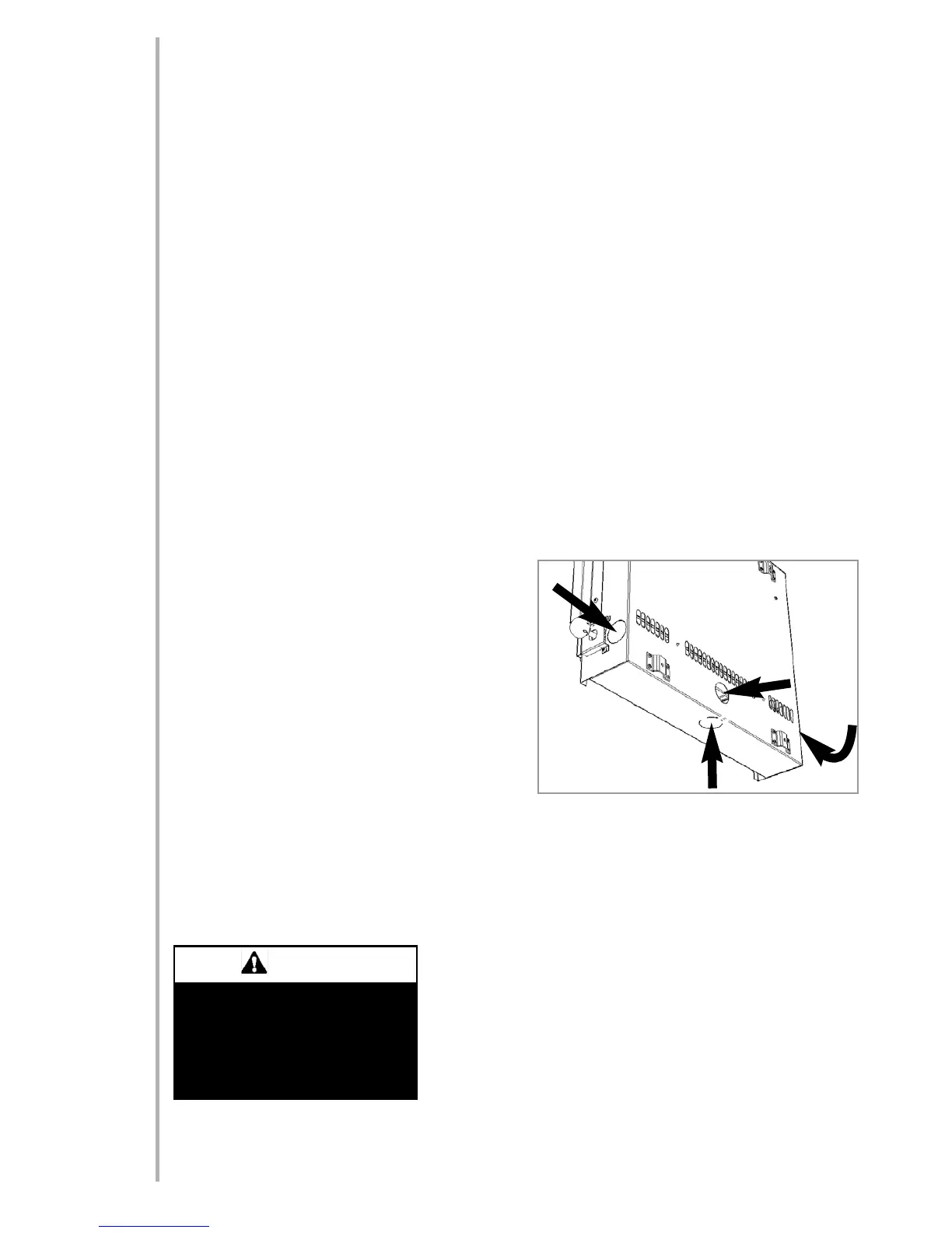
GAS SUPPLY ROUTES
There are four possible entry points for the gas supply pipework to enter the appliance firebox. These entry
points are ‘knock out’ type holes. Non-concealed gas connections may be made using the entry points at either
end of the firebox or the one in the bottom of the firebox. A concealed gas connection may be made using the
knock out hole in the centre back of the firebox. Select the most appropriate entry point and knock out the rel-
evant hole
No more than 1.5m of 8mm diameter pipe must be used
to avoid unnecessary pressure drops.
If a concealed gas connection is to be made, the supply
pipe should always be sleeved through walls and floors
using the shortest possible route. For concealed supply
pipe routing, pipes must (where possible) be vertical and
providing there is sufficient wall thickness available, they
should be placed in pipe chases. Horizontal pipe runs
should be avoided. Prior to chasing a solid wall, an
inspection should be made to note the proximity of any
cables/sockets outlets which may already be buried.
Pipes must be secured using suitable clips and protected against corrosion. Ideally factory finished protected
pipework and fittings should be used. Joints should be kept to a minimum and compression fittings must not be
used. The pipework installation must be tested for soundness before any protection is applied and/or the
pipework and fittings are buried.
FIXING THE APPLIANCE
Remove any protective film coatings from the finished/decorative surfaces of the appliance. After having select-
ed the final mounting position of the appliance, taking into account the requirements as specified in sections 3
and 4 of these instructions, the integrity of the wall, and the feasibility
of the proposed supply pipe routing, the firebox of the appliance may
be secured to the wall.
To ensure customer safety, be sure to design the installation so that the
strength of both the wall and any wall fixings used are sufficient.
Focal Point Fires plc. assumes absolutely no responsibility for injuries
and damages that may occur due to improper installation or handling.
The appliance should not be installed until all wet plastering and/or dry
wall sanding and wall painting has been completed. Do not block the
ventilation holes of the appliance. The wall onto which the appliance is installed must be flat. Install only on a
vertical surface. Avoid sloped surfaces. Installation onto anything other than a vertical wall may result in fire,
damage or injury.
4
5.0
5.1
6.0
4.1
The wall where the appliance is to
be installed must be capable of long-
term support of the total load of the
appliance. Measures should also be
taken to ensure sufficient strength to
withstand the force of earthquakes,
vibration and other external forces.
WARNING
7.0
© 2011 Focal Point Fires plc.