FIXING THE APPLIANCE
If the appliance is to be mounted on the inner leaf of
a conventional cavity brick wall, or a solid wall, then
the wall plugs and fixing screws provided may be
used. Depending on the condition of the wall it may
be necessary to use additional fixings. In this situation,
any additional fixings and wallplugs should be of the
same size and type as the ones provided. At the appro-
priate stage of the installation, drill four holes using
only a 8.0mm masonry bit to a depth of 43mm. Insert
the wallplugs provided ensuring they are flush to the
wall.
If the appliance is to be mounted on a dry lined wall or
a timber framed construction wall then efforts should
be made to fix in at least two positions vertically, into
one of the wooden studs, or supporting wooden
members of the wall using two of the fixing screws
provided. If this is not achievable then the wall should
be strengthened using appropriate building materials.
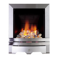
If there is no alternative than to rely on
some
plasterboard fixings then special cav-
ity screw fixings or hollow wall anchors will be required which are not supplied
with this product. These should be constructed from metal and not plastic and of
the design indicated to the right. For further guidance for wall fixing in timber
framed buildings, refer to the current edition of IGE/UP/7.
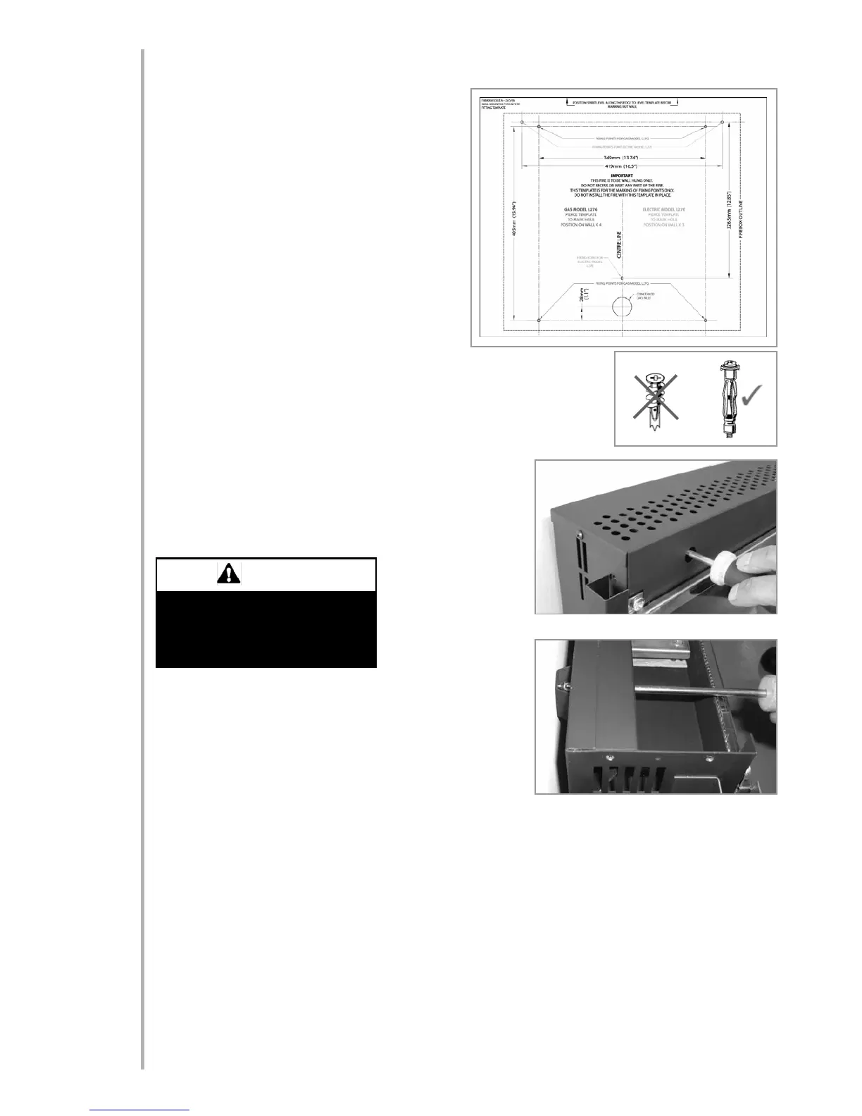
Purist & Serif models: Mark the positions shown as “Fixing points
model L23” on the wall.
Florence & Oxford models: Mark the positions shown as “Fixing
points model P23” on the wall.
If a concealed gas connection is to be made ensure the gas sup-
ply pipe is in it’s final
position and can enter
the appliance in the cor-
rect position when the
appliance is hung on the
wall. Drill the wall as
appropriate for the type
of wall as previously
described in this section, and insert the chosen type of wall fix-
ings. Insert the wall fixing screws into the top wall plugs, taking
care to leave the screws protruding approximately 5mm from the
wall. Now hang the appliance onto these screws through the two
keyhole shaped holes in the upper brackets on the back panel of
the appliance.
Insert the lower fixing screws into the lower wall plugs through the
corresponding fixing holes in the lower part of the back panel. Do
not tighten fully.
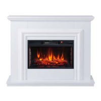
Before tightening the wall mounting screws fully, at this stage it is recommended to check the horizontal align-
ment of the appliance with a spirit level, as small adjustments can still be made if necessary. When this has been
checked, tighten all four fixing screws fully. To access the upper fixing screws insert a screwdriver through the
round access holes in the front face of the outlet grille (as shown). These access holes are located in the same
position on all models. If required the outlet grille can be removed (also shown).
CHECKING THE BURNER
There are no imitation fuel bed components to install. The appliance features a ribbon burner which is designed
to produce a continuous band of flame over it’s length.
The burner should be visually inspected to ensure it is free from any foreign matter.
If it is necessary to clean or dust off the burner then the glass door should be removed by removal of the four
retaining screws. Re-fit the glass door after cleaning or inspection, ensuring the correct orientation and a good
seal.
5
7.0
7.1
Plasterboard alone is not considered
to be a structural material.
It is not recommended to rely on
plasterboard fixings alone to support
the weight of the appliance.
WARNING
© 2011 Focal Point Fires plc.