Brake block
Brake disk
2 mm 0,5 mm
Tech 33
Be particularly careful not to touch the
brake disc with your nger during instal-
lation, removal or maintenance if the disc
is rotating. If you insert your ngers in the
holes in the brake disc, you may suffer
serious injury.
The brake saddle and the disc may be hot
after braking, therefore do not touch them during
or immediately after riding, as you could burn yourself.
Before adjusting the brakes, check that the parts have cooled down sufciently.
Your bicycle may be tted with a disc brake only when appropriate xings
are present on the frame and on the fork. If in doubt, consult a dealer.
If the brake blocks have come into contact with oil or grease they must be
replaced. If the brake disc has come into contact with oil or grease it must be
cleaned, otherwise braking efciency may be strongly impaired.
Check whether or not the quick release lever is located on the right-hand side
(opposite side to the brake disc). If the quick release lever is located on the
same side as the brake disc, there is a danger that the lever and the brake disc
could impair one another
A worn, cracked or bent brake disc must be
replaced. Consult a dealer.
If the thickness of the brake block is less than
0.5 mm, it must be replaced.
Hydraulic Disc Brakes
The hydraulic oil pressure disc brake has a uid reservoir on the brake lever.
The hydraulic uid is fed to the calipers via a tube. The brake blocks are thus
pressed against the wheel rim via the brake pistons. This is a low maintenance
type of brake.
Carry out a braking test after each adjustment by pushing the bicycle
strongly whilst pulling the brake lever. Only use your bicycle when it can be
safely braked.
Check the tubes and connections for leaks each time before riding. Leaking
tubes and connections can result in brake uid leaking out of the braking
system. This can lead to reduced efciency of the brakes.
Do not use the brakes further if oil leaks out; have the appropriate repairs carried
out by a dealer without delay.
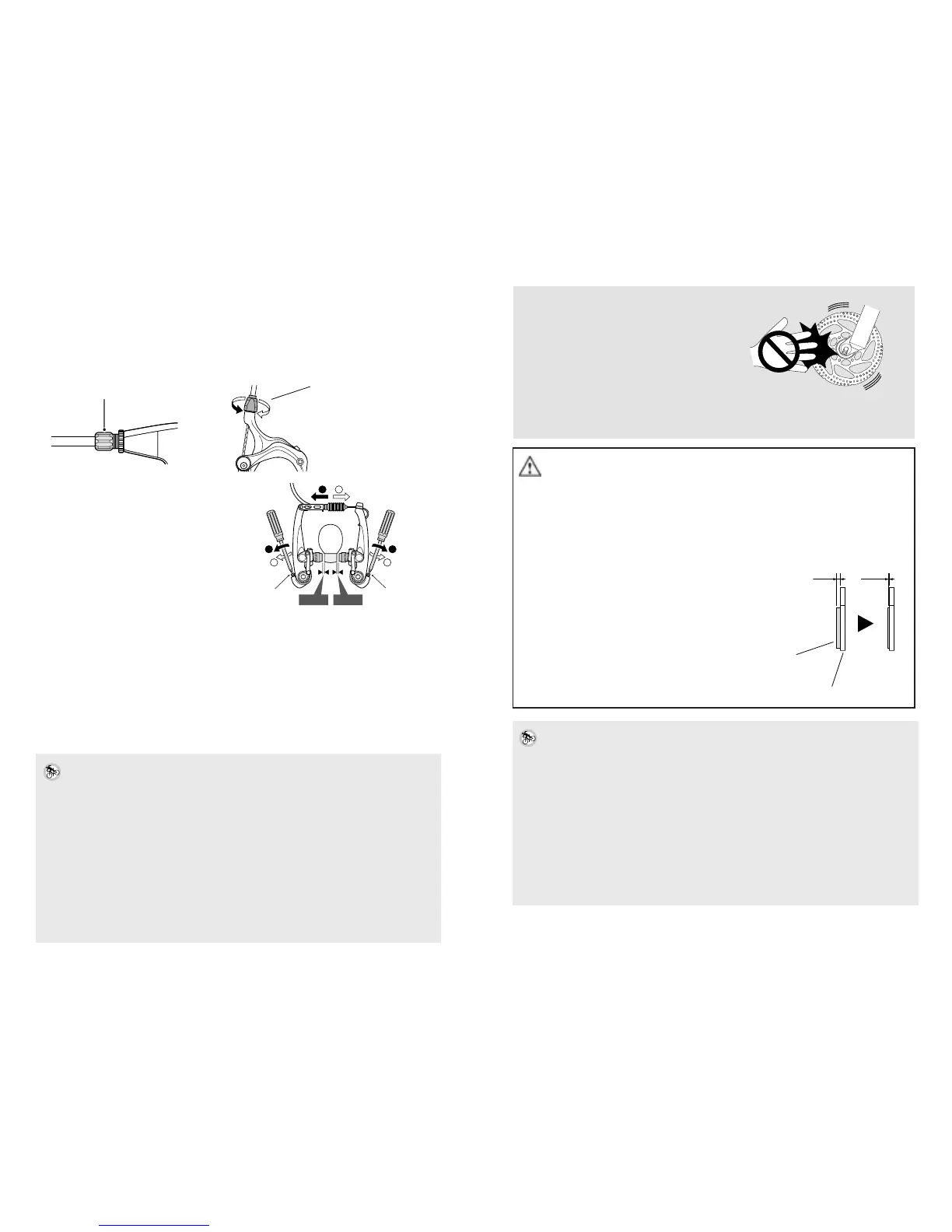
Adjusting the gap between the brake pad and the wheel rim
Turn the cable adjustment screw (adjusting bush). To increase the brake pad
gap, the adjusting screw is turned towards the inside (clockwise). To decrease
the brake pad gap, the adjusting screw is turned towards the outside
(anticlockwise). The gap between the brake block and the wheel rim should
be 1 mm. Adjusting bush Grip width adjusting screw
If necessary, adjust the spring
tension using the spring adjustment
screw so that both brake arms move
symmetrically. Subsequently, check
that the brakes work correctly
(see page 26).
If the brakes do not work correctly, of if the brake blocks are worn to the extent
that adjustment is no longer possible, have the bicycle checked and the brake
blocks replaced by a dealer.
Disc brakes
General safety advice
This type of brake is tted with a brake disc mounted on the hub and a brake
saddle on the frame or on the fork.
Have disc brakes adjusted by a dealer.
Incorrect adjustments can lead to accidents.
Carry out a braking test after each adjustment by pushing the bicycle strongly
whilst pulling the brake lever. Only use your bicycle when it can be safely braked.
Disc brakes require a ‘braking-in’ period. For braking in correctly, read the
manufacturers informations.
Braking power increases within this time. You should therefore be aware during
the braking-in period that the braking power can increase. The same applies
after replacement of the brake blocks or the disc.
If you hear noises when braking, the brake blocks may be worn down to the
wear limit. Allow the brakes to cool down and have the brake block thickness
checked or the brake blocks replaced.
Spring adjustment screw
Cable adjustment screw
Spring
adjustment
screw
Spring
adjustment
screw
1 mm 1 mm
1
2
1
2
1
2