- 13 -
1
2
3
4
4
4
.
.
1
1
.
.
2
2
A
A
l
l
p
p
h
h
a
a
6
6
0
0
4
4
I
I
n
n
t
t
e
e
r
r
n
n
a
a
l
l
A
A
s
s
s
s
e
e
m
m
b
b
l
l
y
y
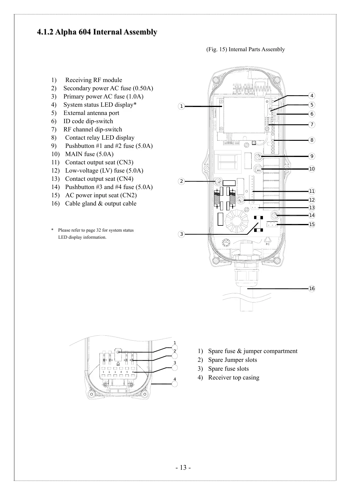
(Fig. 15) Internal Parts Assembly
1) Receiving RF module
2) Secondary power AC fuse (0.50A)
3) Primary power AC fuse (1.0A)
4) System status LED display*
5) External antenna port
6) ID code dip-switch
7) RF channel dip-switch
8) Contact relay LED display
9) Pushbutton #1 and #2 fuse (5.0A)
10) MAIN fuse (5.0A)
11) Contact output seat (CN3)
12) Low-voltage (LV) fuse (5.0A)
13) Contact output seat (CN4)
14) Pushbutton #3 and #4 fuse (5.0A)
15) AC power input seat (CN2)
16) Cable gland & output cable
* Please refer to page 32 for system status
LED display information.
1) Spare fuse & jumper compartment
2) Spare Jumper slots
3) Spare fuse slots
4) Receiver top casing
3
7
6
8
9
10
11
12
14
15
5
13
16
F
U
S
E
F
U
S
E
F
U
S
E
F
U
S
E
F
U
S
E
1
2
4