HVS-100/100OU
HVS-110
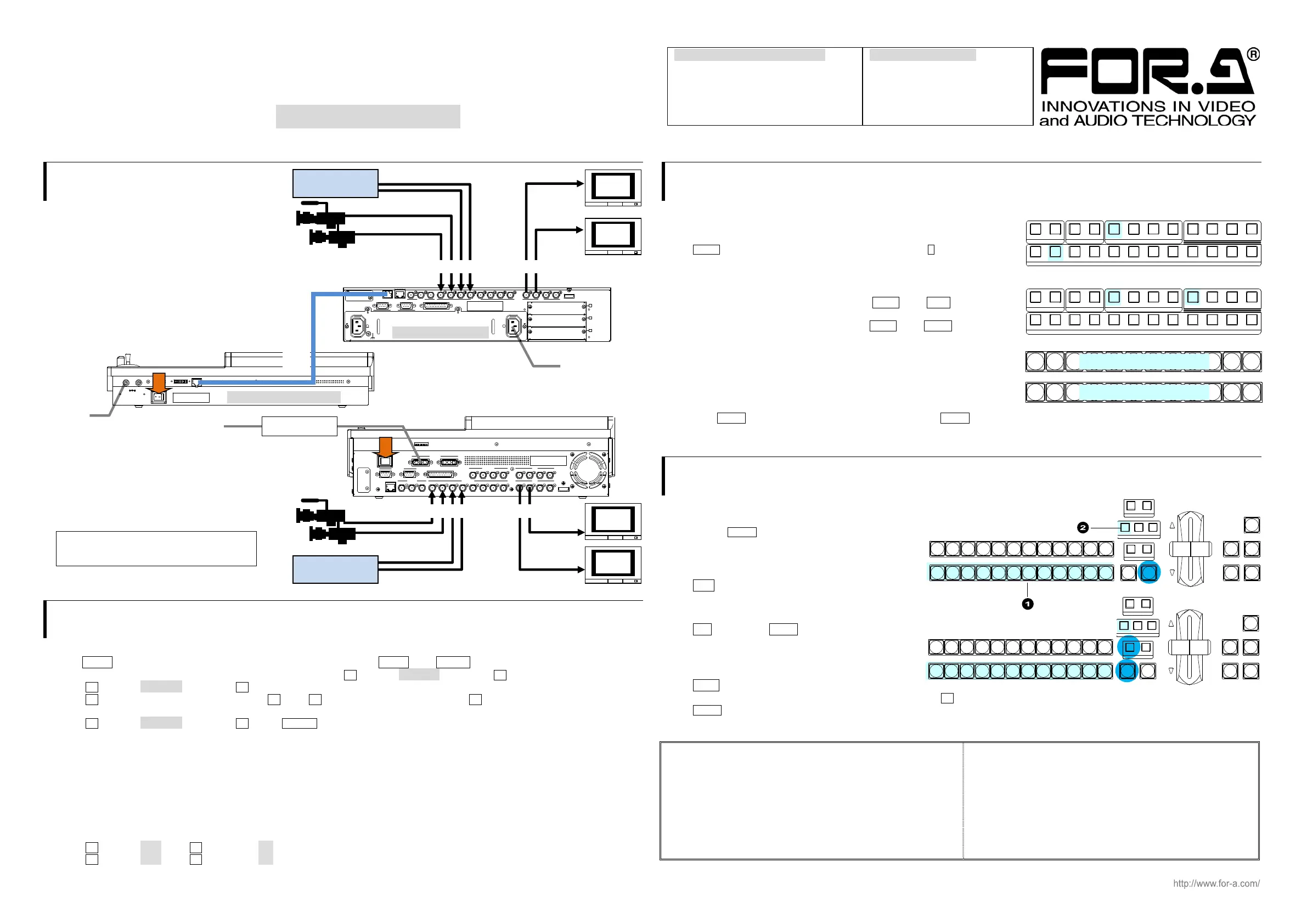
1. Connection
HVS-100/100OU
(1) Connect SDI video signal inputs.
(2) Connect SDI video signal outputs.
(3) Supply power to HVS-100 using
the supplied AC cable.
(4) Supply power to HVS-100OU using
the supplied AC adapter.
(5) Connect HVS-100 and 100OU using
the supplied cable with 100OU.
(6) Turn on power switches on the HVS-100
front panel and the 100OU rear panel.
HVS-110
(1) Connect SDI video signal inputs.
(2) Connect SDI video signal outputs.
(3) Connect the AC adapter to the switcher.
(4) Supply AC power to the AC adapter.
Supply AC power after the AC adapter is
connected to the switcher. Otherwise the
switcher internal parts may be damaged.
(5) Turn on the power switch on the rear panel.
2. Setup
Select the System Signal Format
(1) The MENU button on the control panel should blink at power ON. Press MENU, then SETUP.
(2) The [SETUP] menu top page appears in the menu display. Turn F1 to select SYSTEM, then press F1.
(3) Turn F1 to select FORMAT, then press F1 to display the [SETUP - SYSTEM - FORMAT] menu.
(4) Turn F1 to select the signal format, then press F1. Turn F3 to select aspect ratio, then press F3.
(5) Press the page up button to return to the [SETUP - SYSTEM] menu.
(6) Turn F1 to select REBOOT, then press F1. Press ENTER in the SELECT/KEYPAD block to reboot the switcher.
See section 3-4. "System Signal Format Selection at Initial Use" in the Operation Manual for more details.
Set Date, Time and Time Zone
Open the [SETUP - SYSTEM - TIME] menu to set date, time and time zone.
See section 3-5. "Setting Date, Time and Time Zone at Initial Use" in the Operation Manual for more details.
Set the Frame Synchronizer Function to ON
(1) Open the [SETUP - INPUT - SIGNAL] menu.
(2) Turn F1 to select IN01. Turn F4 to set FS to ON.
(3) Turn F1 to select IN02. Turn F4 to set FS to ON. Set FS to ON for other inputs.
See section 5-7. "Frame Synchronizer" in the Operation Manual for more details.
3. Select Output Video
To Select AUX Output Video
AUX1 outputs the INPUT1 video at initial use.
AUX2 outputs the INPUT1 video at initial use.
Press AUX1 on the left side of the control panel, then press 2 in the
KEY/AUX bus. The AUX1 video will change from INPUT1 to INPUT2.
To Output PGM / PREV Video
To output the program video from AUX1, press AUX1, then PGM
as shown at right.
To output the preview video from AUX2, press AUX2, then PREV.
To Select the PGM / PREV Video
The PGM bus buttons are used to select the PGM (background) video.
The PST bus buttons are used to select the PREV (background) video.
Press a button on the PGM or PST bus to see how the output video changes.
Now, press AUTO in the bottom right of the control panel (with BKGD lit). Or move the fader from end to end.
The AUX1 (PGM) and AUX2 (PREV) video images are switched with each other. This is called a "background transition".
4. Perform Background Transitions
Setup
(1) Select the next video on the PST bus.
(2) Verify that BKGD lights up as shown at right.
If not, press the button to turn on the button light.
To Perform CUT Transitions
Press CUT. The PGM video immediately changes.
To Perform MIX Transitions
Press MIX. Then press AUTO.
(Or move the fader from end to end.)
To Perform Pattern Transitions
Press WIPE.
The [TRANS](1/6) menu will appear on the menu display. Turn F4 to select a pattern.
Press AUTO. (Or move the fader from end to end.)
See section 8-3. "Background Transitions" in the Operation Manual for details on background transitions.
Precautions
- Operate the unit only at the specified supply voltage.
- Ensure the unit is properly grounded at all times.
- Ensure the power cord and connectors are firmly connected.
- Do not install/uninstall cards with power applied to the unit.
- Unit should not be operated or stored with the cover, panels,
and/or casing removed.
- Unit should not be operated or stored in a humid, dusty, etc.
environment. Doing so could result in fire or electrical shock.
- Do not allow fluids, metal fragments, or any other foreign
objects to enter the unit. If foreign matter does enter the unit,
turn the power off and disconnect the power cord immediately.
Remove the material or contact your authorized service
representative.
- If you notice any strange smells or noises coming from the unit,
turn the power off immediately, disconnect the power cord, then
contact your authorized service representative.
111
1
22234
2 3 4 5 6 7 8 9 10 11 12
PG M PR EV CL EAN MV
KEYER DSK AUX
KEY/AUX
111
1
22234
2 3 4 5 6 7 8 9 10 11 12
PG M PR EV CL EAN MV
KEYER DSK AUX
KEY/AUX
PGM
PST
123456789101112
Select the PGM BKGD video
Select the PREV BKGD video
REV NOR/ REV
DIRECTI ON
BLACK
TRANS
BKGD KEY1 KEY2
NEXT TR ANSI TI ON
MI X W I P E
KEY1 KEY2
TRAN SIT ION T YPE
AU TO C U T D S K1 D SK 2
PGM
PST
1 23456789101112
REV NOR/ REV
DIRECTI ON
BLACK
TRANS
BKGD KEY1 KEY2
NEXT TR ANSI TI ON
MI X W I P E
KEY1 KEY2
TRAN SIT ION T YPE
AU TO C U T D S K1 D SK 2
PGM
PST
1 23456789101112
REF OUT 1 123 45678 234REF IN
HDMI OUT
AUX
5678
AUX
LAN
SDI INPUT
9101112
SDI INPUT
GPI IN/TA LLY OUT
DC12V IN
12
MOD E S W
POWER
OFF ON
GE NLOC K
RS-422
12
HD/SD SDI
Video Server,
VTR, etc.
HD/SD SDI
AUX2
Video
AUX1
Video
AC power source
AC adapte
Quick Setup Guide
HVS-100 / 100OU Packing List
HVS-100OU HVS-100
LAN Cable AC Cable
AC Adapter
Quick Setup Guide (This guide)
CD (PDF Operation Manual)
HVS-110 Packing Lis
HVS-110
AC Adapter
Quick Setup Guide (This guide)
CD (PDF Operation Manual)
To AC
dapte
AUX1
Video
AUX2
Video
DC 12V
12
POW ER
OFF ON
MODE SW TO MU
HVS-100OU rear panel
To AC Power source
HD/SD SDI
REF OUT 1
1
2345678
234
A
B
C
REF IN
12
2
AC100-240V 50/60Hz INAC100-240V 50/60Hz IN
1
TO OU
LAN GENLOCK SDI INPUT
RS-422 GPI I N/TALLY OUT
HDMI OUTAUX
Video Server,
VTR, etc.
HVS-100 rear panel
Supplied cable
with 100OU
HD/SD SDI
 Loading...


