EasyManua.ls Logo

FOR-A HVS-490 User Manual

FOR-A HVS-490
241 pages
To Next Page IconTo Next Page
Page #1 background imageLoading...
Page #1 background image
HVS-490
Digital Video Switcher
HVS-492OU
HVS-492WOU
HVS-492ROU
Operation Unit
4
th
Edition - Rev. 1
OPERATION
MANUAL

Table of Contents

Other manuals for FOR-A HVS-490

Questions and Answers:

FOR-A HVS-490 Specifications

General IconGeneral
BrandFOR-A
ModelHVS-490
CategorySwitch
LanguageEnglish

Summary

Precautions and Safety Warnings

Power Precautions

Safety guidelines for operating the unit at the specified supply voltage and handling the power cord.

Grounding Precautions

Ensures proper grounding to prevent electrical shock and avoid dangerous connections.

Operation Precautions

Guidelines for safe operation under hazardous conditions and preventing foreign material entry.

Circuitry Access Precautions

Warnings regarding accessing circuitry with power applied and touching hot components.

Connection and Basic Operation

Basic Connection Example

Illustrates the fundamental connection steps for video sources, reference signals, and power.

Powering On the System

Procedure for powering on the control panel and main unit, including verification of connections.

Selecting System Signal Format

Steps to select the initial signal format and aspect ratio upon first powering on the unit.

Verifying Current Status

How to check M/E, FLEXaKEY, and STILL status using the HOME screen interface.

Panel Descriptions

HVS-490 Panel Layout

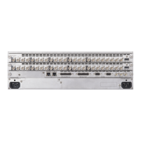
Detailed description of the front and rear panel components of the HVS-490 Main Unit.

Control Panel Layout

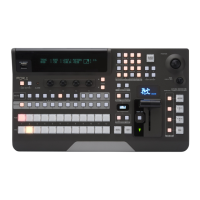
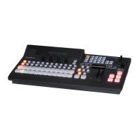
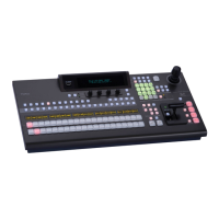
Explanation of the control panel layout for HVS-492OU, HVS-492WOU, and HVS-492ROU units.

Expansion Card Slots

Details on front side and rear side slots for installing function and I/O expansion cards.

Interface Connectors

Pin assignments and descriptions for RS-422 and GPI IN/ALARM connectors.

Switcher System Configuration

Network Settings

Information on factory default IP addresses for connecting the switcher via LAN.

Menu Operation

Setting Menu Parameters

Procedure for adjusting parameters using menu controls, including keypad input and navigation.

Copying and Swapping Settings

Instructions for copying or swapping settings between MEs, MELites, or Keys.

Resetting Menu Settings to Default

Procedures for returning parameters or entire menus to their factory default settings.

Backing Up Settings

Methods for backing up panel settings automatically at startup.

Setting up Video Sources

Adjusting Input Signal Levels

Guide to adjusting input signal levels using Proc Amp and Video Level Clip features.

Mapping Video Sources to Bus Buttons

Assigning video sources to bus buttons for selection across M/E1, M/E2, and AUX buses.

Frame Synchronizer Function

Using the frame synchronizer to synchronize asynchronous signals for all inputs.

Setting up Additional Inputs

Video Outputs

Selecting Video for M/E Outputs

Assigning combined M/E images to M/E OUT1 and M/E2 ports.

Preview and Clean Output Images

Selecting background and key images for PREVIEW, CLEAN 1, and CLEAN 2 outputs.

KEY OUT Signals

Assigning switcher processed key cut signals to AUX outputs and M/E OUT1/2.

Changing AUX Output Images

Selecting video sources and applying simple effects for AUX output switching.

HDMI Output Configuration

Settings for HDMI output ports, including signal format, audio, and UHD modes.

Adjusting Output Signal Levels

Adjusting output signal levels using Proc Amp and Video Level Clip features.

Safety Area Markers

Displaying markers for safety areas and screen center on the desired output.

BUS LINK Function

Linking video switches between buses for synchronous operations.

Bus Operation

Control Panel Overview

Description of the control panel composition and M/E controllers.

Assigning M/Es to LINES

Procedure for assigning M/E buses (M/E1, M/E2) to control panel lines (LINE 1, LINE 2).

Selecting Video Sources

Using bus button rows on the control panel to select video sources.

MELite Operations

Setting up an MELite

Procedure for attaching an AUX bus to an MELite and assigning it to a LINE for operation.

XPT Re-entry Function

Utilizing quadruple crosspoint re-entry for combining video sources and creating complex effects.

Transitions

Transitions on LINE 1 and LINE 2

Performing background, key, and FLEXaKEY transitions on each M/E.

AUX Transitions

Applying simple video effects to AUX bus transitions using menus or control blocks.

Transition Blocks

Overview of LINE 1 and LINE 2 transition blocks and their available buttons.

Black Transitions

Executing fade-to-black transitions using the BLACK TRANS button.

Background Transitions

Performing CUT, MIX, and Pattern transitions for background video sources.

KEY Transitions

Performing CUT, MIX, and Pattern transitions for key images.

Simultaneous Background and Key Transitions

Performing background and key transitions simultaneously for integrated effects.

Simultaneous M/E Transitions (ONStage)

Performing transitions across multiple M/E buses (M/E1, M/E2, AUX1-12) simultaneously.

Pattern (WIPE/DVE) Transitions

Performing pattern transitions for M/E background and keys using WIPE or DVE patterns.

Direct Pattern Function

Saving, recalling, and clearing patterns using direct selection feature.

Modifying Patterns

Changing or modifying preset WIPE and DVE patterns for transitions.

KEY IN/OUT Using Cut or Fade

Performing key transitions using KEY ON AIR, KEY AUTO buttons, and fader lever.

AUX Image Transitions

Switching AUX bus images using effects like fade and slides.

Advanced Transition Settings

Adjusting transition rate, fader limits, offsets, and other advanced parameters.

Key and FLEXaKEY Features

Creating Luminance and Full Keys

Steps to create Luminance Key (Self Key) and Full Key using M/E1 KEY1.

Creating Bus Keys

Using different signals for INSERT and SOURCE for Bus Keys.

Adjusting Key Signal Parameters

Adjusting key signal and its composition using Clip, Gain, Transparency, and FAM.

Chroma Key Setup

Setting up chromakeys using CK1 to create key signals from chroma components.

Creating a Chroma Key

Steps to create a chroma key by selecting background and key signals.

Chroma Key Adjustments

Fine-tuning chroma key generation using Back Color, Key/Fill signals, and FG Suppression.

Assigning DVE Channels

Assigning DVE Channels to Buses (LINE DVE)

Applying DVE effects to individual buses for effects like reduction, rotation, and lighting.

DVE Effects

Changing DVE Image Position and Size

Adjusting DVE image position and size using the joystick or menu controls.

Color Correction

Adjusting Colors

Adjusting signal levels using Color Correction modes (Balance, Differential, Sepia) and RGB components.

Clip Adjustment

Adjusting signal level thresholds (Clip) in Y/C or RGB modes for color correction outputs.

Still and Clip Store

Still Images (STILL)

Capturing, loading, and displaying still images using M/E program outputs.

Video Clips (CLIP)

Recording and playing video clips, stored in a separate memory buffer.

Storing Still and Video Images (HVS-49SSD240G)

Automatically backing up images to SSD and restoring them.

Multiview Output

Assigning Multiview to AUX Bus

Assigning multiviewer channels to AUX or HDMI outputs using bus buttons or menus.

Event Memory

Recalling Events

Loading saved events using DIRECT mode or the RECALL button.

Loading Event at Start-up

Recalling panel setup at switcher startup by loading a saved event.

Sequence Function

Basic Sequence Operations

Creating, storing, loading, and playing sequences using one bus, M/E1 BKGD.

Sequence Group Operation

Managing multiple buses in sequences by grouping them for flexible operations.

Macro Operations

Recording Macros

Recording sequences of operations as macros for single-button execution.

Executing Macros

Loading and executing recorded macros using the MACRO menu and number buttons.

Macro Memory Operation

Managing macro memory, including overwrite protection, naming, and deletion.

Macro Execution Buttons

Assigning macros to KEY/FLX bus buttons for execution.

File Operations

Saving Data to SD Card

Procedure for saving all switcher settings, including system and event data, to an SD card.

Loading Data from SD Card

Loading panel settings, events, macros, or sequences from an SD card to the switcher.

System Setup Settings

Selecting System Mode (Signal Format)

Choosing the signal format and aspect ratio for the switcher.

Control Panel Setup

Reboot and Initialization

Rebooting the system and resetting various settings to factory defaults.

External Device Connections

GPI Control Interface

Controlling external devices or being controlled via GPI interface, including tally output.

Tally Output

Outputting tally information from GPI/TALLY OUT connectors and the GPI I/O connector.

Router Control

Connecting and controlling a router for crosspoint switching via RS-422.

AUX Bus Control Box Setup

Connecting and checking AUX boxes for remote control of AUX outputs and events.

Editor Control

Controlling the switcher from an editor via RS-422 interface using HVS-2000ED software.

VTR Control

Controlling video tape or disk recorders via RS-422 using the VTR protocol.

VDCP Operation

Controlling VCR or Video Disk Recorders via RS-422 or LAN using VDCP protocol.

4K (UHD) Mode Support

Switching to 4K Mode

Steps to switch to 4K mode, selecting SQD or 2SI, and resetting parameters.

Updating the System Software

Troubleshooting

Event Memory Operations

Storing Events

Saving panel settings as events for quick recall, up to 100 events.

Loading Events

Loading saved events using DIRECT mode or the RECALL button.

Related product manuals