132
18. Multiview Output
The multiviewer allows you to monitor multiple images such as video sources input to the switcher and
internally generated or combined images on the same screen. The switcher provides 3 multiviewer
channels (MV1-MV3*), with each output having various types of split displays: 2, 4, 5, 7, 9, 10, 11, 13
and 16 way.
This chapter use MV1 as an example, but other MV channel operations are the same.
Note that the multiviewer outputs are delayed by one frame relative to the program output.
* 2 channels are available in SD formats.
The setup procedure for the multiviewer is as follows:
1. Assign a multiviewer video to an AUX output bus.
2. Select a split-screen type.
3. Select video for each split area. (Clock display available instead of video)
4. Add titles, audio level meters, safety area markers, on-air tallies and frame borders.
18-1. Assigning a Multiview Image to an AUX Bus
The multiviewer channels can be assigned to any AUX or HDMI outputs.
To assign to AUX outputs, use the buttons in BUS SELECT block on the control panel, or set on the
[SETUP > OUTPUT > AUX OUT] menu.
To assign to HDMI outputs, set on the [SETUP > OUTPUT > HDMI OUT] menu.
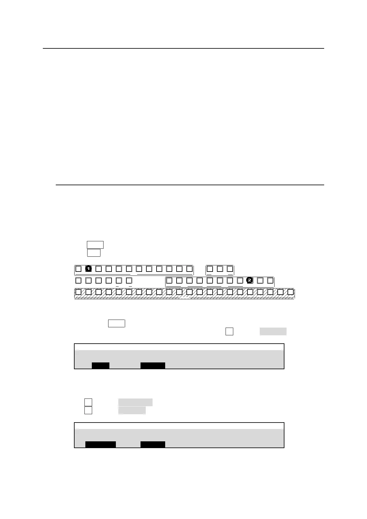
Assigning MV1 to AUX2 using the BUS SELECT Buttons
(1) Press AUX2 in the BUS SELECT block.
(2) Press MV1 above the KEY/AUX bus.
1 2 3 4 5 6 7 8 9 10 11 12
1 2 3 4 5 6 7 8 9 10 11 12 13 14 15 16 17 18 19 20 21 22
CUT MIX WIPE
AUX TRANSITION
M/E1 M/E2
PGM OUT1 OUT2 OUT3 PGM OUT1 OUT2 OUT3 MV1 MV2 MV3
KEY/AUX
AUX
KEY1 KEY2 KEY3 KEY4 1 2
UTILITY
Assigning MV1 to AUX2 using the Menu
(1) Quickly press AUX2 twice in the BUS SELECT block.
(2) The [SETUP > OUTPUT > AUX OUT] menu opens. Turn F2 to select MV1 OUT.
Assigning MV1 to HDMI OUT1 using the Menu
(1) Open [SETUP > OUTPUT > HDMI OUT] menu PAGE 1.
(2) Turn F1 to select HDMI OUT1.
(3) Turn F2 to select MV1 OUT.
SETUP > OUTPUT > HDMI OUT