106
12-7-1. Where FLEXaKEY1-4 Appear
FLEXaKEY1 and 2 images appear on combined M/E1 images and FLEXaKEY3 and 4 on
M/E2 as factory default. Users can change the destination of FLEXaKEY1-4 to another bus.
To do so, follow the procedure below.
(1) Open the [M/E FLEXaKEY > FLX1-4 > TRANS > ASSIGN] menu.
(2) Go to PAGE 9. Turn F1 to select an output destination.
Select the destination for other keys in the same way.
M/E FLEXaKEY > FLX1 > TRANS > ASSIGN
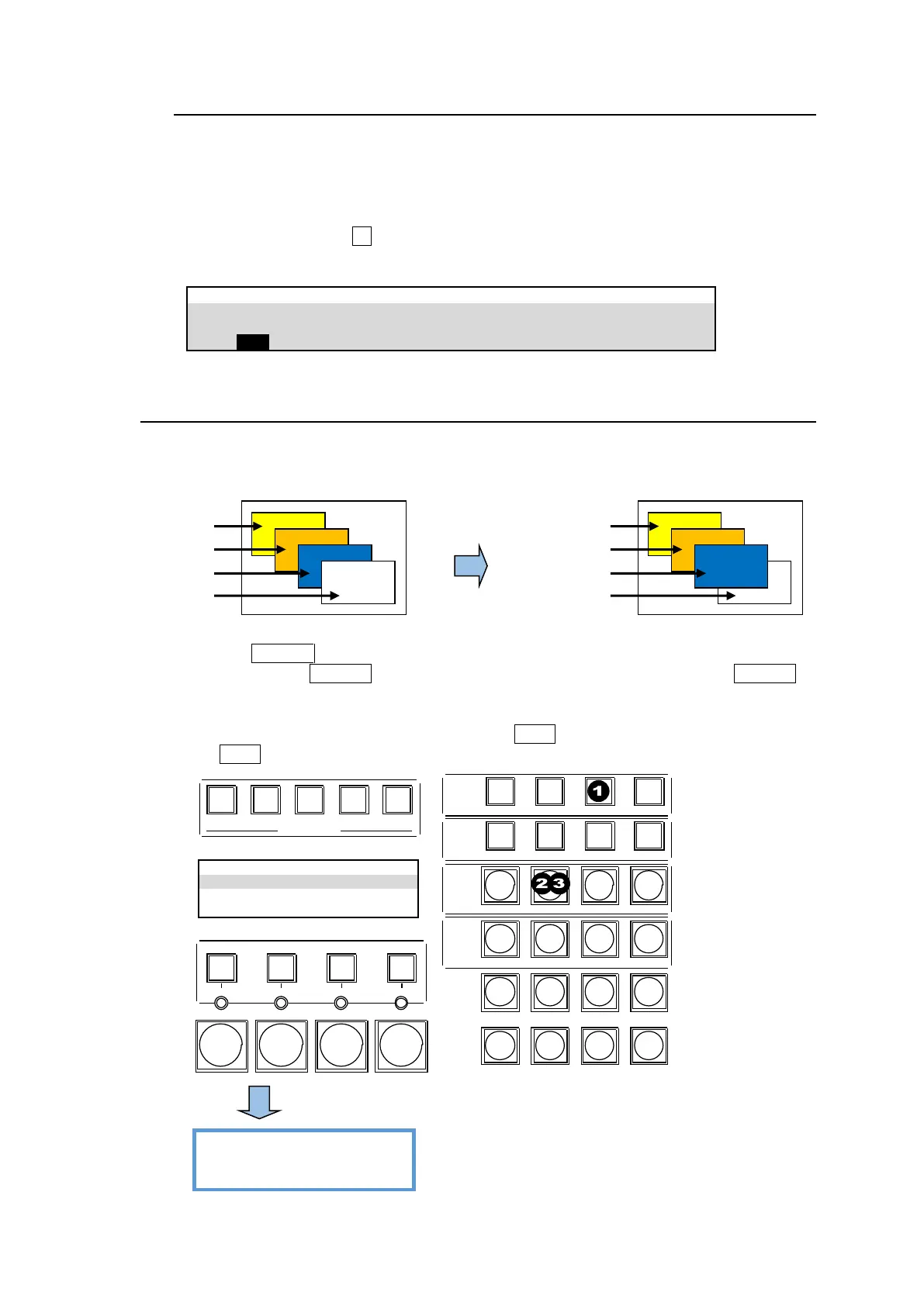
12-8. Changing Key Layer Order
Layer order for Keys or FLEXaKEYs can be changed respectively in M/E1 and M/E2.
This chapter explains how to switch the KEY2 and KEY1 layers on the M/E1 as an example.
Using the KEY PRI button
(1) Press and hold the KEY PRI button on the CONTROL block. While holding down KEY PRI, a
key layer matrix is displayed on the KEY information display. Layer 1 is the bottom layer and
located just above the background.
(2) If the M/E1 KEY1-KEY4 buttons are not lit, press KEY2 to select the KEY2 layer line.
(3) Press KEY2 again to move up the layer stack.
6 7 8 9 10
USER BUTTON
CONTROL
MEMORY
M/E1
M/E2
MENU LOCK KEY PRI PAGE
DIREC T PATT MACRO EVENT SEQUENCE
INC
DEC
7 8 9
4 5 6
1 2 3
0
RECALL STORE
ENTER
CLEAR
+ / -
CK WIPE SUB EFF
FLX4FLX3FLX2FLX1
KEY1 KEY2 KEY3 KEY4
KEY1 KEY2 KEY3 KEY4
KEY1 KEY2 KEY3 KEY4
DVE DVE DVE DVE
ON AIR