177
25-2-2. Tally Output Settings (GPI /TALLY OUT)
To change GPI/TALLY OUT connector pin assignments (See Sec. 3-4-3. “GPI I/O Connector“),
proceed as follows.
(1) Set tally colors for output buses. (See Sec. 25-2-1. “Tally Color Settings.”)
(2) Open the [SETUP > GPI TALLY > GPI OUT] menu.
(3) Turn F1 to select the pin number.
(4) Turn F2 to select TALLY under TYPE.
(5) Select a tally color under FUNC/COL and a tally signal under TARGET/XPT. (See “GPI
OUT/TALLY Functions in Appendix 2.)
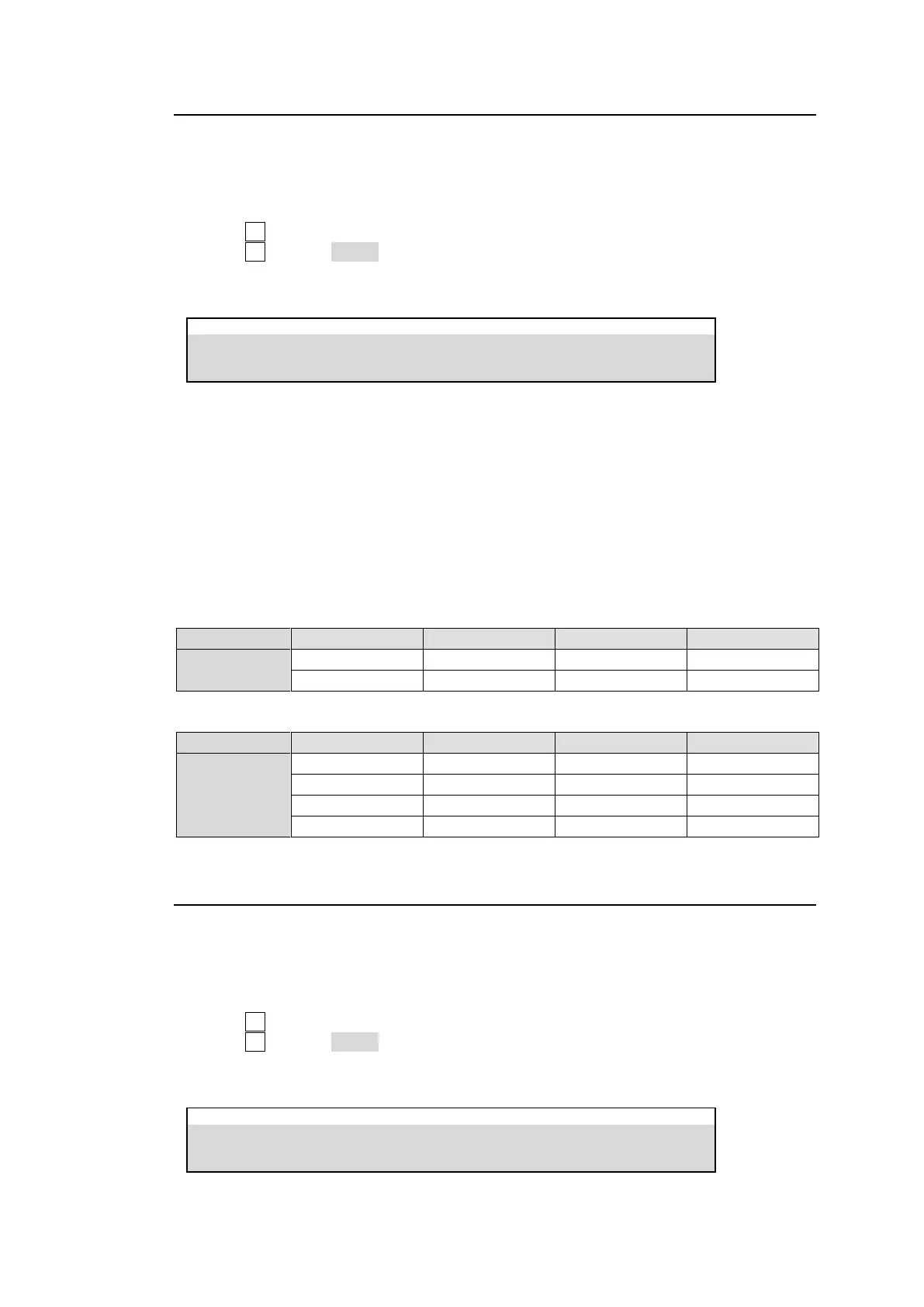
SETUP > GPI TALLY > GPI OUT
Tally Control Example
The setting example in the tables below shows how to configure tally settings to perform the
following operations: Pin 1 and 2 send On-air tallies and Pin 9 and 10 send Next tallies.
Conditions
A RED tally is used to indicate On-Air (M/E1 PGM bus).
A GREEN tally is used to indicate a next background signal (M/E1 PST bus).
Pin 1 and 2 output RED tallies for IN01-IN02 respectively.
Pin 9 and 10 output GREEN tallies for IN01-IN02 respectively.
TALLY COLOR menu settings
GPI OUT menu settings
25-2-3. Tally Output Settings (GPI I/O)
To change pin assignments of the GPI I/O connector on the control panel (See Sec. 3-4-3.
“GPI I/O Connector“), proceed as follows.
(1) Set tally colors for output buses. (See above.)
(2) Open the [PANEL > OU GPI I/O > GPI OUT] menu.
(3) Turn F1 to select the pin number.
(4) Turn F2 to select TALLY under TYPE.
(5) Select a tally color under FUNC/COL and a tally signal under TARGET/XPT. (See “GPI
OUT/TALLY Functions in Appendix 2.)
PANEL > OU GPI I/O > GPI OUT