195
25-7. VTR Control
The switcher can control video tape or video disk recorders via RS-422 using the VTR (Sony 9-pin)
protocol. Up to 2 channels are available. Connect a device to a desired RS-422 port, configure the
port and select a channel for VTR following the procedures in this chapter.
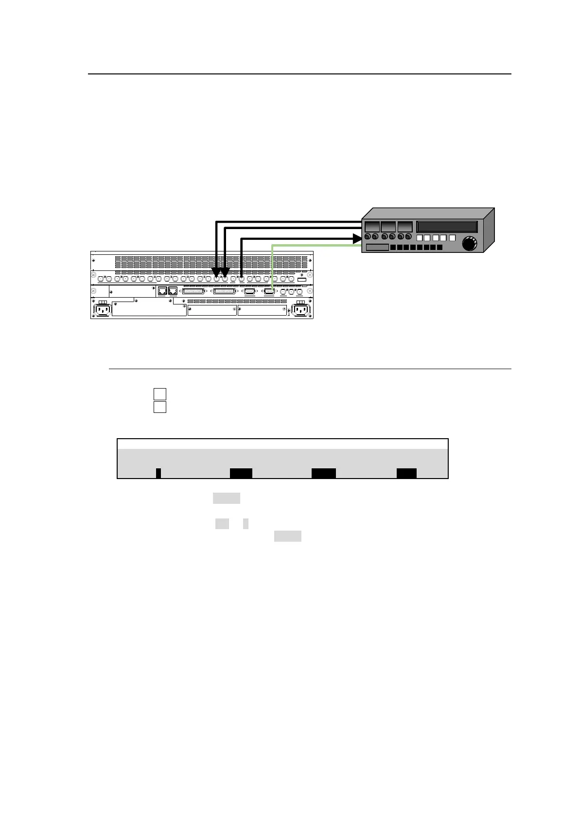
System Configuration Example
(1) Connect HVS-490 to a VTR using an RS-422 port and configure the port.
(2) Assign a VTR channel to the RS-422 port. (See Sec. 25-7-1.)
(3) Control the VTR using the VTR menu (see Sec. 25-7-2) or using USER buttons (see Sec.
24-3).
25-7-1. Assigning VTR Channel to an RS-422 Port
(1) Open the [SETUP > SYSTEM > RS-422] menu.
(2) Turn F1 to select the RS-422 port number.
(3) Turn F2 to assign a VTR channel (VTR1 to 4) to the port.
(4) Set BAUDRATE and PARITY according to your VTR device.
Setting BAUDRATE to 38400 may cause a malfunction in some cases. In such cases, take
any one of the following measures and reconnect the router.
Change Stop Bit to 1.5 or 2 in the router
Change the switcher baudrate to 39300.
SDI INPUT HDMI
65431 21615141312111098765431 2 21
M/E AUX
OPTION SLOT BOPTION SLOT A
AC100-240V 50/60Hz IN
2 1
AC100-240V 50/60Hz IN
REF IN REF OUT
GENLOCKGPI/TALLY OUTGPI IN/ALARMLAN
HVS(OU) EXT
1 2
RS-422