111
14. DVE Effects
This chapter shows how to apply DVE effects to M/E2KEY1 as an example. Assume that LINE DVE is
set to ON for M/E2KEY1. (See Sec. 13-2-2. “Enabling LINE DVE on a BUS.") In this example, the KEY1
image, to which DVE effects is applied, is called “DVE image.”
14-1. Changing Position and Size
Let’s change the position and size of a DVE image using the menu or joystick.
Using the Joystick
Open the [M/E FLEXaKEY > M/E2 > KEY1> MODIFY > DVE POS/SIZE] menu.
To change the DVE image position, move the joystick up, down, left, or right.
To change the DVE image size, twist the joystick clockwise or counter-clockwise.
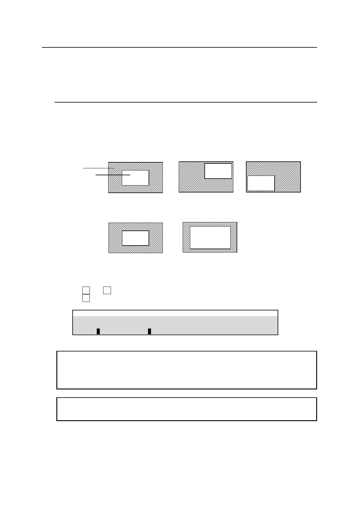
The figures below are examples when POSITION (X, Y) is set to (0, 0).
Using the Menu
(1) Open the [M/E FLEXaKEY > M/E2 > KEY1> MODIFY > DVE POS/SIZE] menu.
(2) Turn F1 and F2 to change the DVE image position.
(3) Turn F3 to change the DVE image size.
M/E FLEXaKEY > M/E2 > KEY1 > MODIFY > DVE POS/SIZE
The base POSITION of the DVE image is originally the center of the output screen. You can set
the position of the image by specifying X and Y coordinates, with the origin of the axes located at
screen-center.
Setting the size allows users to change the size of key images while retaining aspect ratios. If the
value is 1,000, the key images will be full-screen size.
The POS/SIZE STEP parameter in [M/E FLEXaKEY > M/E1 > BKGD PGM > MODIFY >DVE
INIT/SETUP] menu PAGE 12 allows you to change increments to 1/1000 or 1/4096 to enable
finer settings.