197
25-8. VDCP Operation
The switcher can control a VCR or Video Disk Recorder through RS-422 or LAN using VDCP
protocol. Up to 4 channels (device connections) are available. Follow the procedure below to
perform VDCP communication and RS-422 port settings.
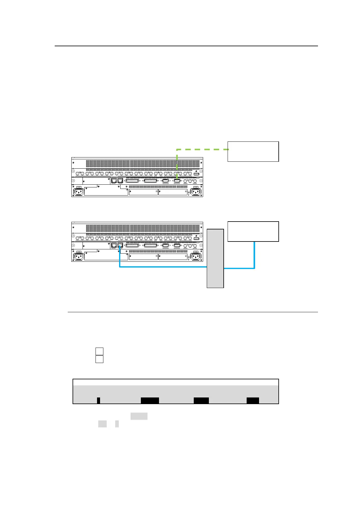
System Configuration Example
(1) Connect a VDCP device to HVS-490 via RS-422 or LAN.
If using RS-422, assign a VDCP channel to an RS-422 port and set communication settings.
If using LAN, change the VTR connection to LAN (Ethernet) and configure LAN connection
between the HVS-490 and VDCP device.
(2) Operate the VDCP device using the VDCP menu (see Sec. 0), or using User buttons (see. Sec.
24-3. "USER Button.")
25-8-1. RS-422 Connection Settings
To use an RS-422 connection, assign a VDCP channel to an RS-422 port on the switcher,
then set communication settings as shown below:
(1) Open the [SETUP > SYSTEM > RS-422] menu.
(2) Turn F1 to select an RS-422 port for VDCP channel connection.
(3) Turn F2 to select a VDCP channel (VDCP1-4).
(4) Set BAUDRATE and PARITY according to the VDCP device.
Setting BAUDRATE to 38400 may cause a malfunction in some cases. In such cases, change
Stop Bit to 1.5 or 2 in the router
SDI INPUT HDMI
65431 21615141312111098765431 2 21
M/E AUX
OPTION SLOT BOPTION SLOT A
AC100-240V 50/60Hz IN
2 1
AC100-240V 50/60Hz IN
REF IN REF OUT
GENLOCKGPI/TALLY OUTGPI IN/ALARMLAN
HVS(OU) EXT
1 2
RS-422
SDI INPUT HDMI
65431 21615141312111098765431 2 21
M/E AUX
OPTION SLOT BOPTION SLOT A
AC100-240V 50/60Hz IN
2 1
AC100-240V 50/60Hz IN
REF IN REF OUT
GENLOCKGPI/TALLY OUTGPI IN/ALARMLAN
HVS(OU) EXT
1 2
RS-422