54
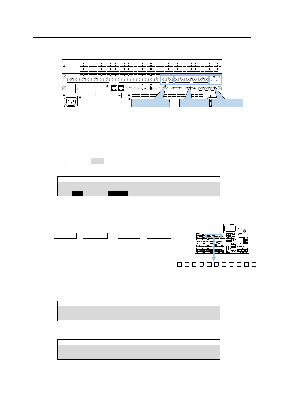
8. Video Outputs
Three output types are provided: M/E1 and M/E2 ports are for combined M/E images and both AUX1-6
and HDMI ports can output input video sources as well as combined M/E and multiview images.
SDI INPUT HDMI
65431 21615141312111098765431 2 21
M/E AUX
OPTION SLOT BOPTION SLOT A
AC100-240V 50/60Hz IN
2 1
AC100-240V 50/60Hz IN
REF IN REF OUT
GENLOCKGPI/TALLY OUTGPI IN/ALARMLAN
HVS(OU) EXT
1 2
RS-422
8-1. Selecting Video for M/E OUT 1-2
M/E1 and M/E2 ports on the MU rear panel are dedicated to output combined M/E video images.
Select M/E images for OUT1-4 in the menu as shown below.
(1) Open the [SETUP > OUTPUT > M/E OUT] menu.
(2) Turn F1 to select OUT1.
(3) Turn F2 to select a combined image.
8-1-1. Selecting OUT 1-3 Images on M/E 1-2
Combined M/E1 and M/E2 images can be easily
assigned to AUX or KEY buses by using buttons
M/E1PGM to M/E1OUT3 and M/E2PGM to M/E2OUT3
and various types of mixed M/E images, including PGM,
PVW, CLEAN1, CLEAN2 and KEY OUT, can be assigned
to the M/E1OUT1-3 and M/E2OUT1-3 buses.
(1) Open the [PANEL > BUS CONTROL > M/E OUT]
menu.
(2) If setting the menu as shown below, the PVW image is assigned to the M/E1OUT1 bus.
PANEL > BUS CONTROL > M/E OUT
If setting the menu as shown below, the PVW image is assigned to the M/E2OUT1 bus.
PANEL > BUS CONTROL > M/E OUT
M/E1 M/E2
PGM OUT1 OUT2 OUT3 PGM OUT1 OUT2 OUT3 MV1 MV2 MV3