47
7. Setting up Additional Inputs
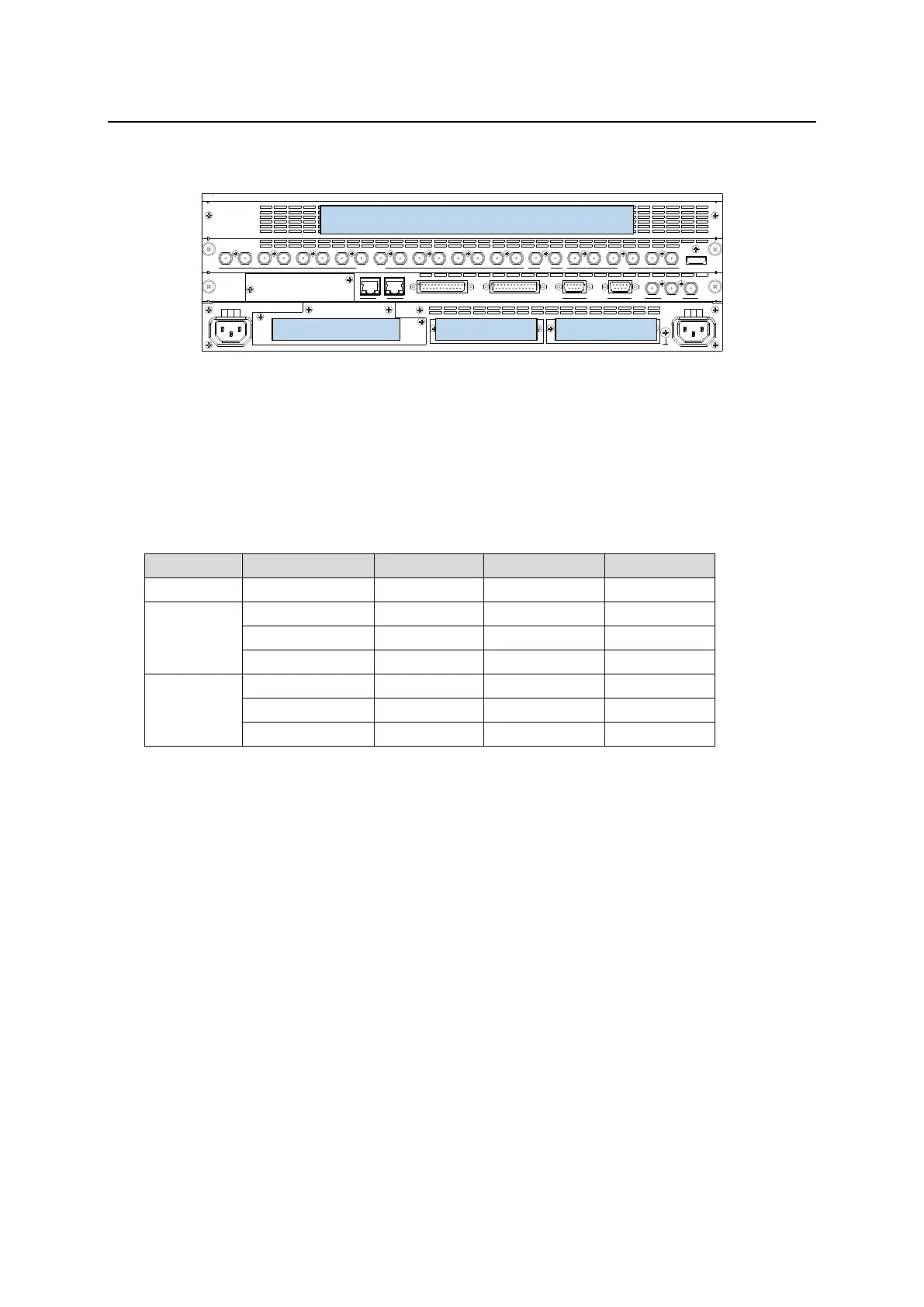
Additional input/output cards can be installed into SLOT A, SLOT B and 49IO SLOT.
Install an HVS-49AES card to the dedicated 49AES SLOT.
SDI INPUT HDMI
65431 21615141312111098765431 2 21
M/E AUX
OPTION SLOT BOPTION SLOT A
AC100-240V 50/60Hz IN
2 1
AC100-240V 50/60Hz IN
REF IN REF OUT
GENLOCKGPI/TALLY OUTGPI IN/ALARMLAN
HVS(OU) EXT
1 2
RS-422
Each channel of expansion cards can be independently set.
Sequence numbers are given to signal names in the order of 49IO SLOT, SLOT A and SLOT B optional
inputs (although they can be changed). Use these names to set up additional input signals.
Output bus numbers are fixed to AUX13-20, as shown in the above table. Use these numbers to set up
additional output signals.
See Sec. 6-3. "Changing Video Source Names" for details on signal name changes.
See Sec. 6-2. "Mapping Video Sources to Bus Buttons" for signal source assignments.
Proc Amp, Frame Synchronizer, Input Still and Side Panel
Almost the same functions as those for standard inputs can be applied to additional inputs, such as
Frame Synchronizer and Input Still.
See Sec. 6-1. "Mapping Video Sources to Bus Buttons" for signal level adjustments.
See Sec. 6-4. "Frame Synchronizer."
See Sec. 17-3. "Still Image Display using FS Buffer (INPUT STILL)."
Proc Amp, Safety Area Marker and Color Correction
Almost the same functions as those for standard outputs can be applied to additional outputs, such
as Proc Amp, Safety Area Marker, and Color Correction.
See Sec. 8-4. "Adjusting Output Signal Levels" to 8-7. "BUS LINK Function" for details.