31
4. Switcher System Configuration
HVS-490 (MU) and control panel (OU) units should be connected via LAN, directly or using a network
hub. Use a network hub if adding external devices such as AUX units or computers to the switcher
system.
Direct Connection
Use the supplied LAN cable to connect the HVS-490 LAN (HVS) port to the control panel HVS LAN port.
(See Sec. 2-1. Basic Connection Example.)
Using a Network Hub
(1) Use the supplied LAN cable to connect the HVS-490 LAN (HVS) to a network hub.
(2) Use the user-supplied LAN cables to connect the control panel LAN (HVS) to the hub.
(3) To connect external devices, use the user-supplied LAN cables to connect the devices to the
HVS-490 LAN (EXT) port via the hub.
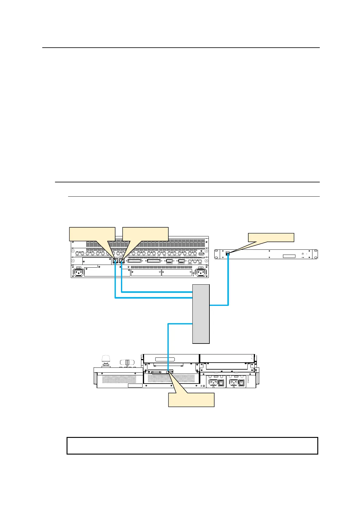
4-1. Network Settings
4-1-1. Factory Default IP Addresses
As factory default, IP addresses and netmask are set as shown in the figure below. To change
these settings, open each relevant menu page. To apply changes, reboot the system. (See
Sec. 24-4. "Reboot and Initialization.")
When connecting to an existing network, consult your network administrator regarding the
LAN settings. Use the appropriate cables, hubs and configuration settings.
GPI I/O HVS LAN
POWER1
AC100-240V 50/60Hz IN
POWER
ON
OFF
POWER2
AC100-240V 50/60Hz IN
POWER
ON
OFF
SDI INPUT HDMI
65431 21615141312111098765431 2 21
M/E AUX
OPTION SLOT BOPTION SLOT A
AC100-240V 50/60Hz IN
2 1
AC100-240V 50/60Hz IN
REF IN REF OUT
GENLOCKGPI/TALLY OUTGPI IN/ALARMLAN
HVS(OU) EXT
1 2
RS-422
192.168.0.12 / 24
(HVS LAN)
192.168.0.10 / 24
(LAN (HVS))
192.168.1.10 / 24
(LAN (EXT))